Air condition system of heat pipe storing energy

An air-conditioning system and heat pipe technology, applied in the field of heat-pipe energy storage air-conditioning systems, can solve the problems of no delivery, no matching, and inability to adapt to the urban power grid, and achieve the effects of reducing corrosion, small heat transfer resistance, and reducing installed capacity

Inactive Publication Date: 2007-07-25
NANJING UNIV
View PDF0 Cites 9 Cited by
  • Summary
  • Abstract
  • Description
  • Claims
  • Application Information

AI Technical Summary

Problems solved by technology

[0004] (2) Urban power consumption is growing rapidly, but the urban power grid cannot adapt to it, resulting in a situation where there is no power to be sent or distributed
[0010] At present, in the domestic and foreign markets, there are very few air-conditioning systems that can satisfy cooling (heat), cold storage (heat) and cooling (heat) at the same time.

Method used


Image

  • Air condition system of heat pipe storing energy

Examples


Embodiment Construction

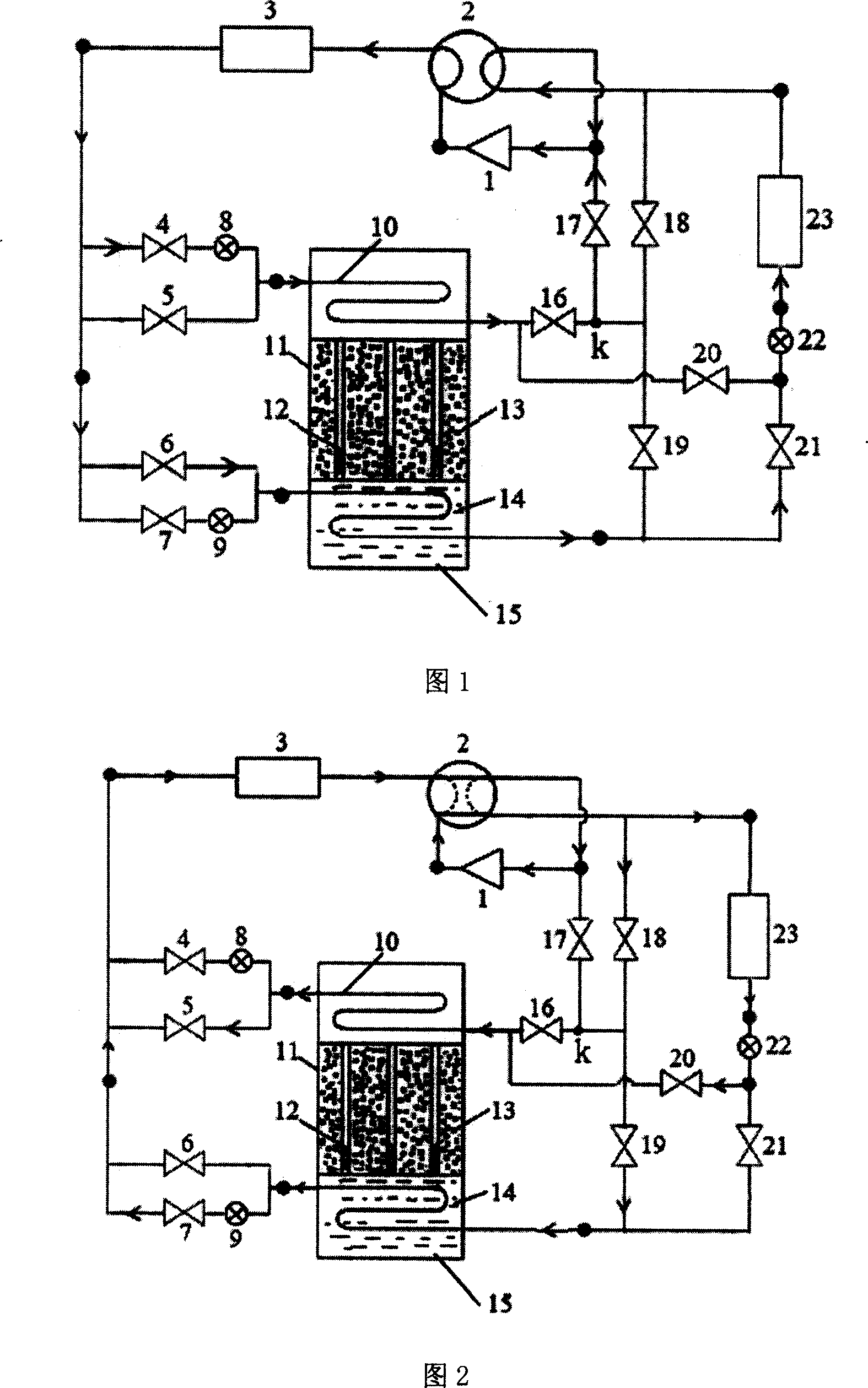
[0038] A heat pipe cold storage air conditioning system according to the present invention is composed of two parts: an indoor unit 23 and an outdoor unit. The indoor unit 23 is composed of a fan and a heat exchange coil. The outdoor unit specifically includes a compressor 1, a four-way reversing valve 2, an outdoor heat exchanger 3, a heat pipe accumulator 11, 10 solenoid valves from the first to tenth, and 3 throttle valves from the first to the third.

[0039]Heat pipe accumulator 11 is made of upper compartment, lower compartment and energy storage material room, upper heat exchanger 10 is installed in the upper compartment, lower heat exchanger 15 is installed in the lower compartment, and energy storage material room is installed Heat pipes 12, heat pipes 12 are arranged in an equilateral triangle in the energy storage material chamber, that is, the line connecting the centerlines of three adjacent heat pipes forms an equilateral triangle, and the length and number of he...


PUM


Abstract

The present invention discloses a heat-pipe energy storage air-conditioning system. It includes indoor machine set and outdoor machine set. The indoor machine set is formed from fan and heat-exchanging coiled pipe, and the outdoor machine set is composed of compressor, four-way reversal valve, outdoor heat-exchanger and heat-pipe energy storage device. Besides, said invention also provides the connection mode of indoor machine set and outdoor machine set.

Description

1. Technical field [0001] The invention relates to a refrigeration air conditioner, in particular to a heat pipe energy storage air conditioner system. 2. Background technology [0002] Since the reform and opening up, my country's comprehensive national strength and people's living standards have been greatly improved. Although my country's electric power industry has made considerable progress, the increase in electric power still cannot meet the needs of the rapid development of the national economy and the sharp increase in people's daily electricity consumption, and the power shortage situation in the country still exists. At present, the tight power supply is mainly manifested in the following aspects: [0003] (1) The load rate of the power grid is low, the peak-to-valley difference of the system increases, and the peak power is seriously insufficient, resulting in frequent power cuts in the power grid. The peak-to-valley difference accounts for more than 30% of the...

Claims


Application Information

Patent Timeline
Patent Type & Authority Applications(China)
IPC IPC(8): F24F5/00
Inventor 方贵银杨帆张曼李辉
Owner NANJING UNIV
Why Eureka
Try Eureka