Method for monitoring porefilling capability of copper electroplating solution

A technology of copper electroplating solution and electroplating solution, applied in the direction of electrolysis process, electrolysis components, material electrochemical variables, etc., to achieve the effect of improving productivity, promoting scientific research progress and reducing cost

Inactive Publication Date: 2007-07-25
ROCKWOOD ELECTROCHEM ASIA
View PDF0 Cites 19 Cited by
  • Summary
  • Abstract
  • Description
  • Claims
  • Application Information

AI Technical Summary

Problems solved by technology

[0008] The purpose of the present invention is to overcome the defects in the existing filling method of electroplating copper, and provide a method for monitoring the filling ability of copper electroplating solution with a new structure. The technical problem to be solved is to provide a method for monitoring copper electroplating The method of liquid filling ability can be used to solve the shortcomings of traditional monitoring methods that can only monitor the concentration change of a single additive in the electroplating formula, while ignoring the influence of the interaction between additives on the electroplating formula

Method used


Image

  • Method for monitoring porefilling capability of copper electroplating solution
  • Method for monitoring porefilling capability of copper electroplating solution
  • Method for monitoring porefilling capability of copper electroplating solution

Examples


example 1

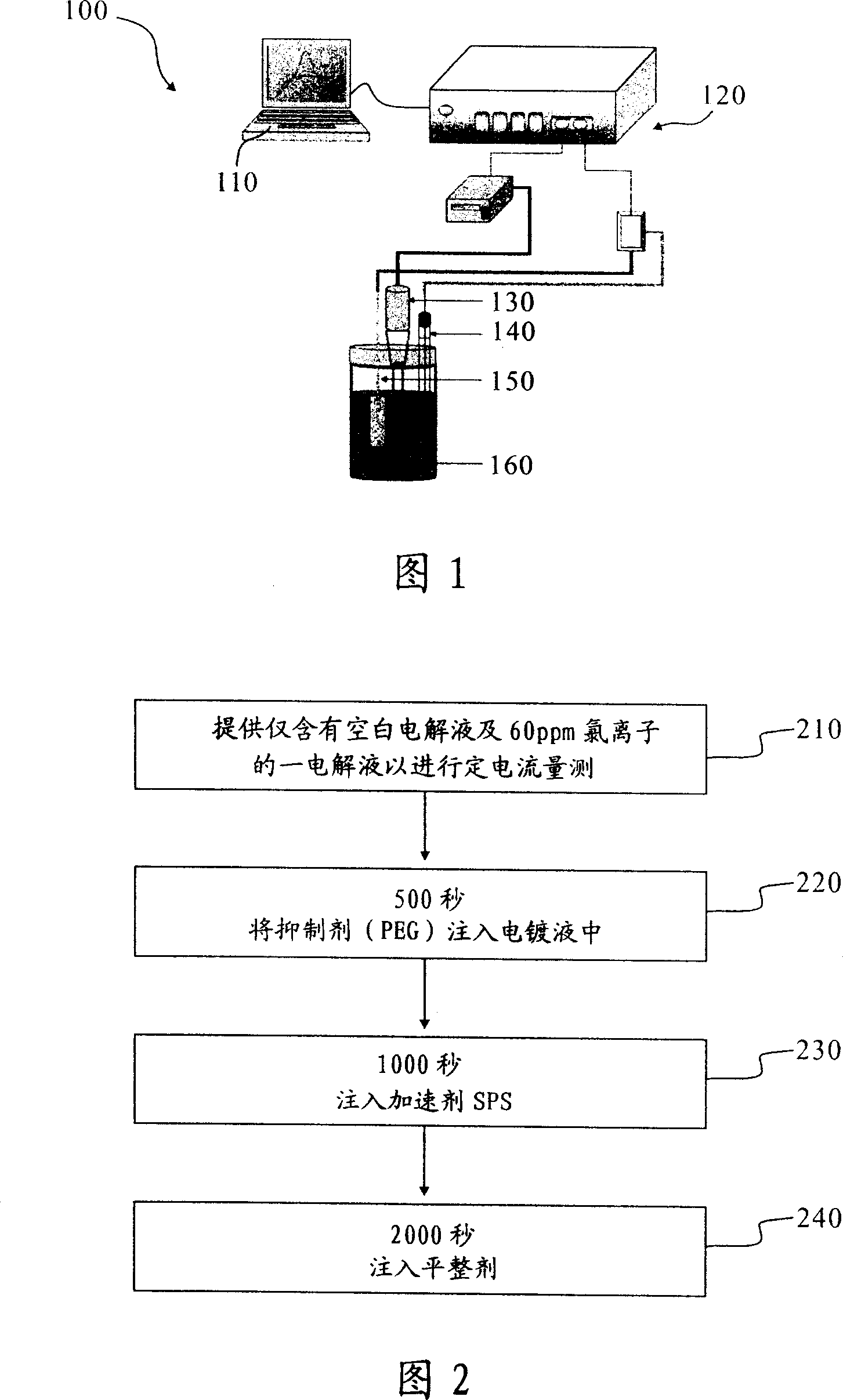
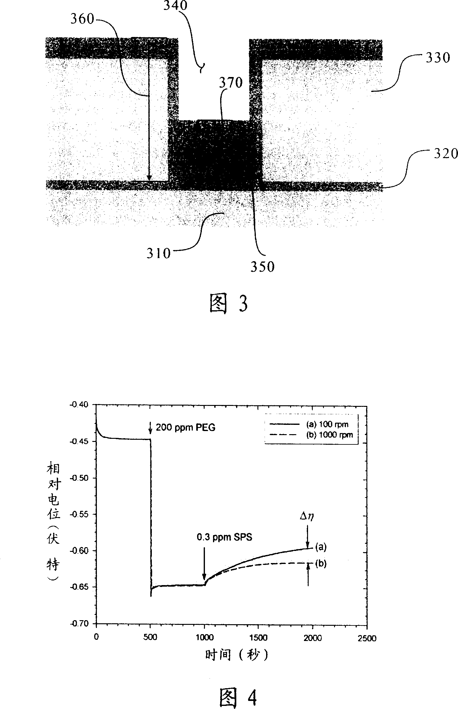
[0062] Please refer to Figure 4. Based on the blank electrolyte and 60ppm of chloride ions, when the constant current measurement is carried out to 500 seconds, 200ppm of inhibitor (PEG) is injected, and then 0.3ppm is injected at 1000 seconds. Accelerator (SPS) is used for constant current measurement, and its relative potential is measured at different electrode rotation speeds to observe the effect on hole filling ability without leveling agent. A potential difference (Δη) can be obtained from the measurement results at two rotational speeds, which is the potential difference obtained by subtracting the potential measured at 1000 rpm from the potential measured at 100 rpm as the hole filling ability index. If the potential difference is positive, it means that the formula has the ability to fill holes, otherwise, if the potential difference is negative, it means that the filling cannot be performed.

[0063] The results show that the electroplating formula shown in Figure ...

example 2

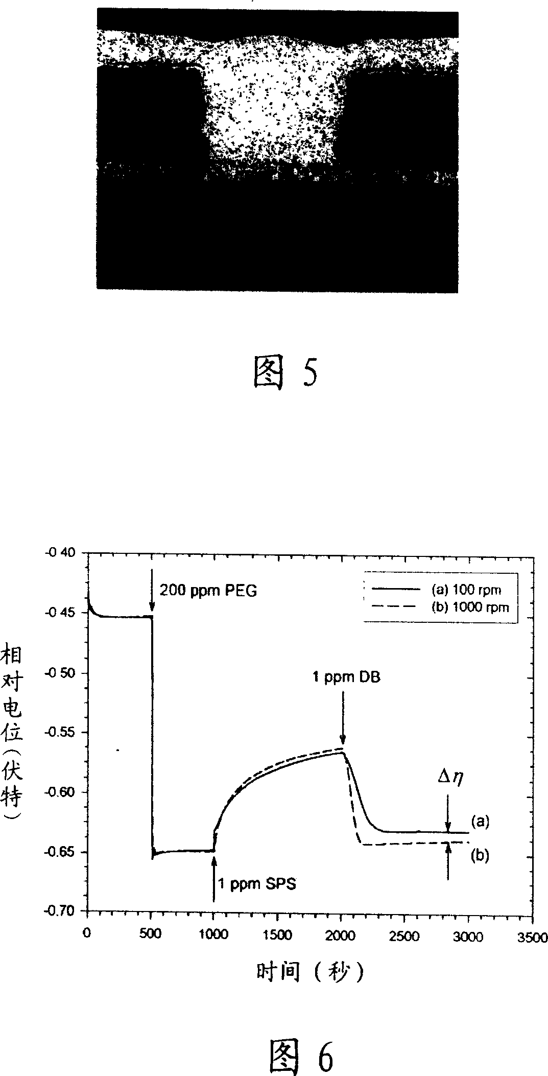
[0067] Please refer to Figure 6, when the SPS concentration in the formulation is increased from 0.3ppm to 1ppm, the predicted pore filling ability is shown. When 1ppm of SPS was injected into the basic plating solution containing 200ppm inhibitor (PEG) and 60ppm chloride ions, the relative potential measured at high electrode rotation speed (1000rpm) was low (dotted line b), while at low rotation number (1000rpm) The measured relative potential is higher (solid line a), and there is a negative potential difference between the two, so it can be known that this formula should not have the ability to fill holes. This result can be attributed to the excessive accelerated deposition of copper on the blind hole plate due to the excessively high SPS concentration. The interaction of ions with the accelerator SPS at a concentration of 0.3 ppm was destroyed. Therefore, uniform deposition of copper on the blind hole plate can also be seen in the cross-sectional view of the hole in Fig...

example 3

[0070] Please refer to Figure 9, where the DB is changed to JGB injected at 1ppm. The result shows that the relative potential (dotted line b) of the rotating electrode at a rotation speed of 1000 rpm is higher than that at a rotation speed of 100 rpm (solid line a). Compared with Figure 6, the potential difference is larger, so it is predicted that this formula should have good hole filling ability. Next, please refer to the cross-sectional view of the hole in Figure 10. The holes electroplated with this formula really show a good hole filling result, which is consistent with the constant current measurement result in Figure 9.

[0071] Continuing to refer to Figure 10, there is no semicircular protrusion on the top of the copper-deposited hole, but a flat surface. Compared with Figure 5, it should be attributed to the fact that JGB can improve the inhibitor (PEG )Effect. This result also shows that in electroplating, if there is no strong inhibitory effect produced by the i...


PUM

PropertyMeasurementUnit
diameteraaaaaaaaaa
diameteraaaaaaaaaa
depthaaaaaaaaaa

Abstract

A method for monitoring hole-filling ability of copper electroplating liquid includes utilizing copper rotary electrode to obtain the first relative potential value of electroplating preparation under the first rotating speed and obtain the second relative potential value of electroplating preparation under the second rotating speed, calculating out potential D-value between two obtained relative potential values and confirming that hole-filling ability is more stronger when potential D-value is more large.

Description

technical field [0001] The invention relates to a method for monitoring the hole filling ability of copper electroplating solution, in particular to a constant current measurement applicable to monitoring the change of hole filling ability of electroplating bath solution used for a long time and predicting the hole filling ability of electroplating solution Law. Background technique [0002] Most of today's printed circuit boards use electroplating copper to make metal wires and fill the guide holes connecting the upper and lower layers. Various additives must be added to the electroplating copper plating solution to speed up the copper deposition rate at the bottom of the blind hole and reach the bottom of the hole. Bottom up filling phenomenon, so the analysis and control of the concentration of additives in the plating solution is an important topic in current research. [0003] In the process of electroplating copper deposition in blind vias, different filling results w...

Claims


Application Information

Patent Timeline
Patent Type & Authority Applications(China)
IPC IPC(8): G01N27/26C25D21/12C25D3/38H05K3/40
Inventor 窦维平柳政伟
Owner ROCKWOOD ELECTROCHEM ASIA
Why Eureka
Try Eureka