Device for automatic controlling final position of moving element

A technology of automatic control device and moving parts, applied in the direction of control using feedback, can solve the problems of high frequency conversion cost, high motor power, high cost, and achieve the effects of good performance, low control accuracy and cost reduction

Inactive Publication Date: 2007-07-25
张挺胜
View PDF0 Cites 7 Cited by
  • Summary
  • Abstract
  • Description
  • Claims
  • Application Information

AI Technical Summary

Problems solved by technology

[0002] There are many examples where the motor drives the moving parts and requires automatic and precise positioning of the final position, such as the lifting movement of the work roll in the roller plate straightening machine of metallurgical forging equipment and the horizontal movement of the work roll in the roll plate bending machine. The reduction amount, the opening amount and the horizontal movement amount all require automatic and precise control of their final positions. Another example is that the uncoiling, leveling and shearing production line of the coil steel plate needs to accurately control the length of the steel plate cut each time, and the speed of the main drive motor needs to be adjusted. And to detect the length of the output steel plate (or the angle of the work roll). Due to the high power of the motor, the cost of using a stepping motor or servo motor is high, and the cost of using a common motor for frequency conversion is also high, and sometimes the effect is not ideal

Method used


Image

  • Device for automatic controlling final position of moving element
  • Device for automatic controlling final position of moving element
  • Device for automatic controlling final position of moving element

Examples


Embodiment 1

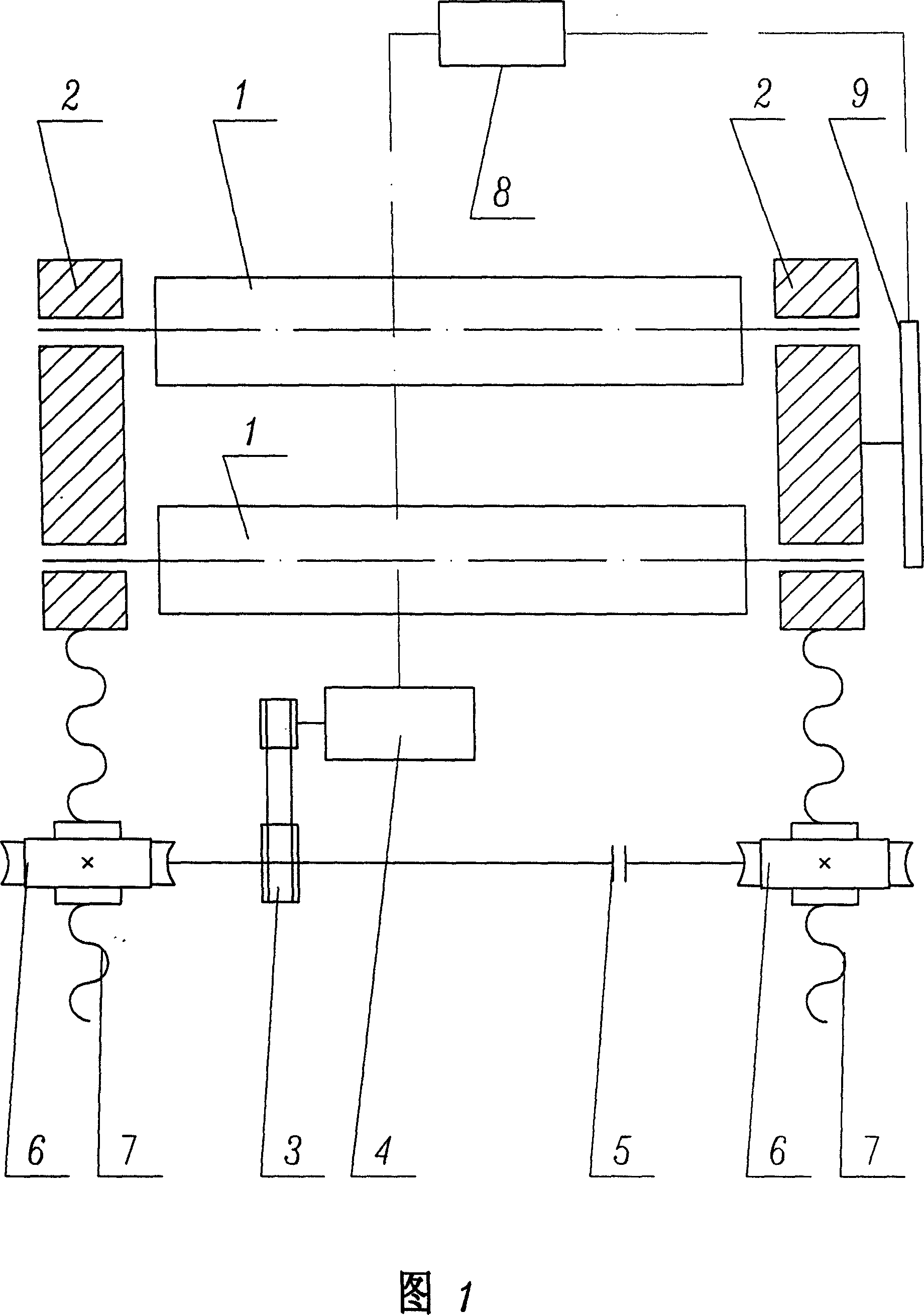
[0018] As shown in Figure 1, it is an embodiment of using the automatic control device for the final position of the moving parts for the horizontal movement of the lower roller of the horizontally adjustable roller plate bending machine. The transmission device is a sprocket 3, a connecting shaft and a flange connector 5, a worm gear pair 6, and a screw nut pair 7; the moving parts are the lower roller bearing housing 2 and the lower roller 1. The displacement sensor is located at the bearing seat 2 of the lower roller. The lower roller moves horizontally on the guide rail of the bed corresponding to the upper roller, and the double-speed motor 4 drives the lower roller bearing housing 2 and the The lower roller 1 moves horizontally, and the motor frequency conversion module is set in the control system 8. The size of the motor frequency conversion module is configured according to the low-speed pole power of the two-speed motor 4. The horizontal movement of the lower roller...

Embodiment 2

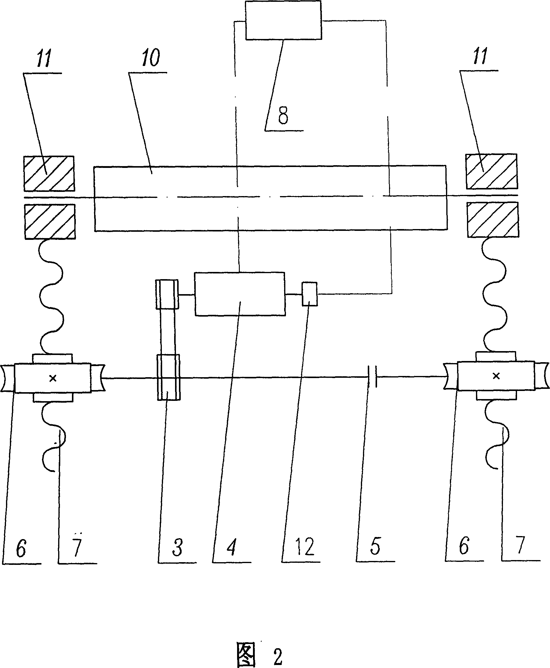
[0020] As shown in Figure 2, it is an embodiment of using the automatic control device for the final position of the moving parts for the mechanical lifting movement of the upper roller of the roller plate bending machine. The transmission device is a sprocket 3, a connecting shaft and a flange connector 5, a worm gear pair 6, and a screw nut pair 7; the moving parts are the upper roller bearing housing 11 and the upper roller 10. The upper roller moves up and down corresponding to the lower roller, and the double-speed motor 4 drives the upper roller bearing seat 11 and the upper roller 10 to move up and down through the sprocket 3, the connecting shaft and the flange connector 5, the worm gear pair 6, and the screw nut pair 7 , the displacement sensor (rotary encoder 12) is set on the shaft of the two-speed motor 4, the size of the motor frequency conversion module in the control system 8 is configured according to the low-speed pole configuration of the two-speed motor 4, an...

Embodiment 3

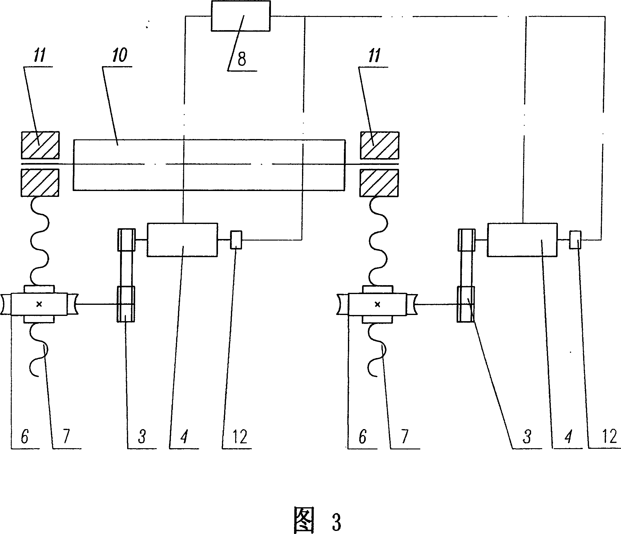
[0022] As shown in Figure 3, it is an embodiment of using the automatic control device for the final position of the moving part for the mechanical lifting movement of the upper roller of the roller plate bending machine. The transmission device is a sprocket 3, a connecting shaft and a flange connector 5, a worm gear pair 6, and a screw nut pair 7; the moving parts are the upper roller bearing housing 11 and the upper roller 10. The control system 8 uses the control device described in Embodiment 2 to control the upper roller bearing housings 11 at both ends of the upper roller 10, the displacement sensor (rotary encoder 12) is arranged on the shaft of the two-speed motor 4, and the control system 8 controls the upper roller 10. The final positions of the upper roll bearing housings 11 at both ends meet the requirements of the set value with a certain accuracy. Because the upper roller chocks 11 at the two ends of the upper roller 10 control the lifting respectively, the worm...


PUM


Abstract

A device used for automatically controlling position of movable component is prepared for setting displacement transducer on movable component, connecting said displacement transducer to input of data collection module through signal line and output of data collection module to input of CPU microprocessor, connecting output of CPU microprocessor separately to motor change-pole module (MCPM) and input of motor frequency conversion module and output of MCPM to various change-pole interface of change-pole multi-speed motor as well as output of MCPM to low speed pole interface of change-pole multi-speed motor.

Description

technical field [0001] The invention relates to a position control device of a moving part, in particular to a device with high final position control accuracy of a moving part. Background technique [0002] There are many examples where the motor drives the moving parts and requires automatic and precise positioning of the final position, such as the lifting movement of the work roll in the roller plate straightening machine of metallurgical forging equipment and the horizontal movement of the work roll in the roll plate bending machine. The reduction amount, the opening amount and the horizontal movement amount all require automatic and precise control of their final positions. Another example is that the uncoiling, leveling and shearing production line of the coil steel plate needs to accurately control the length of the steel plate cut each time, and the speed of the main drive motor needs to be adjusted. And the length of the output steel plate (or the angle of work rol...

Claims


Application Information

Patent Timeline
Patent Type & Authority Applications(China)
IPC IPC(8): G05D3/12
Inventor 张挺胜张本源张先荣张挺锋
Owner 张挺胜
Why Eureka
Try Eureka