Rotor of multipole internal rotor permanent magnet generator

A permanent magnet generator and rotor-type technology, which is applied in the manufacture of stator/rotor bodies, magnetic circuits, electric components, etc., can solve problems such as miniaturization, light weight and thinning, and achieve temperature reduction and energy saving Manufacturing cost, effect of improving power generation efficiency

Inactive Publication Date: 2007-07-25
WUXI KIPOR POWER CO LTD
View PDF2 Cites 5 Cited by
  • Summary
  • Abstract
  • Description
  • Claims
  • Application Information

AI Technical Summary

Problems solved by technology

[0003] The permanent magnet rotor used in the generator generally adopts the outer rotor type, and can only be made into a low-power generator. When the permanent magnet rotor is used in the inner rotor of the motor, most of them have a rotating shaft and a bearing support method. This structure is difficult to make to miniaturization, weight reduction and thinning

Method used


Image

  • Rotor of multipole internal rotor permanent magnet generator
  • Rotor of multipole internal rotor permanent magnet generator
  • Rotor of multipole internal rotor permanent magnet generator

Examples


Embodiment Construction

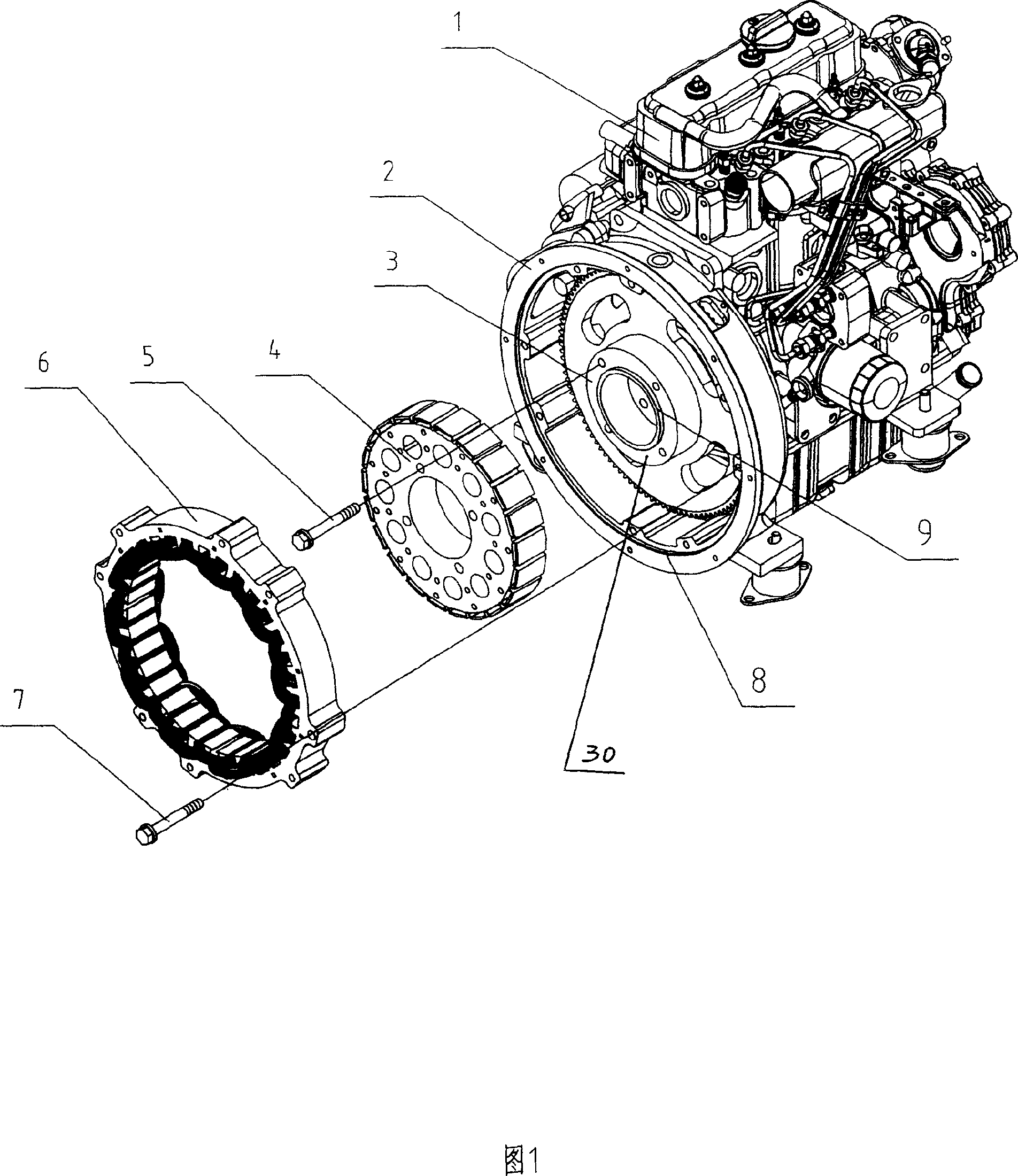
[0020] Below the present invention will be further described in conjunction with the embodiment in the accompanying drawing:

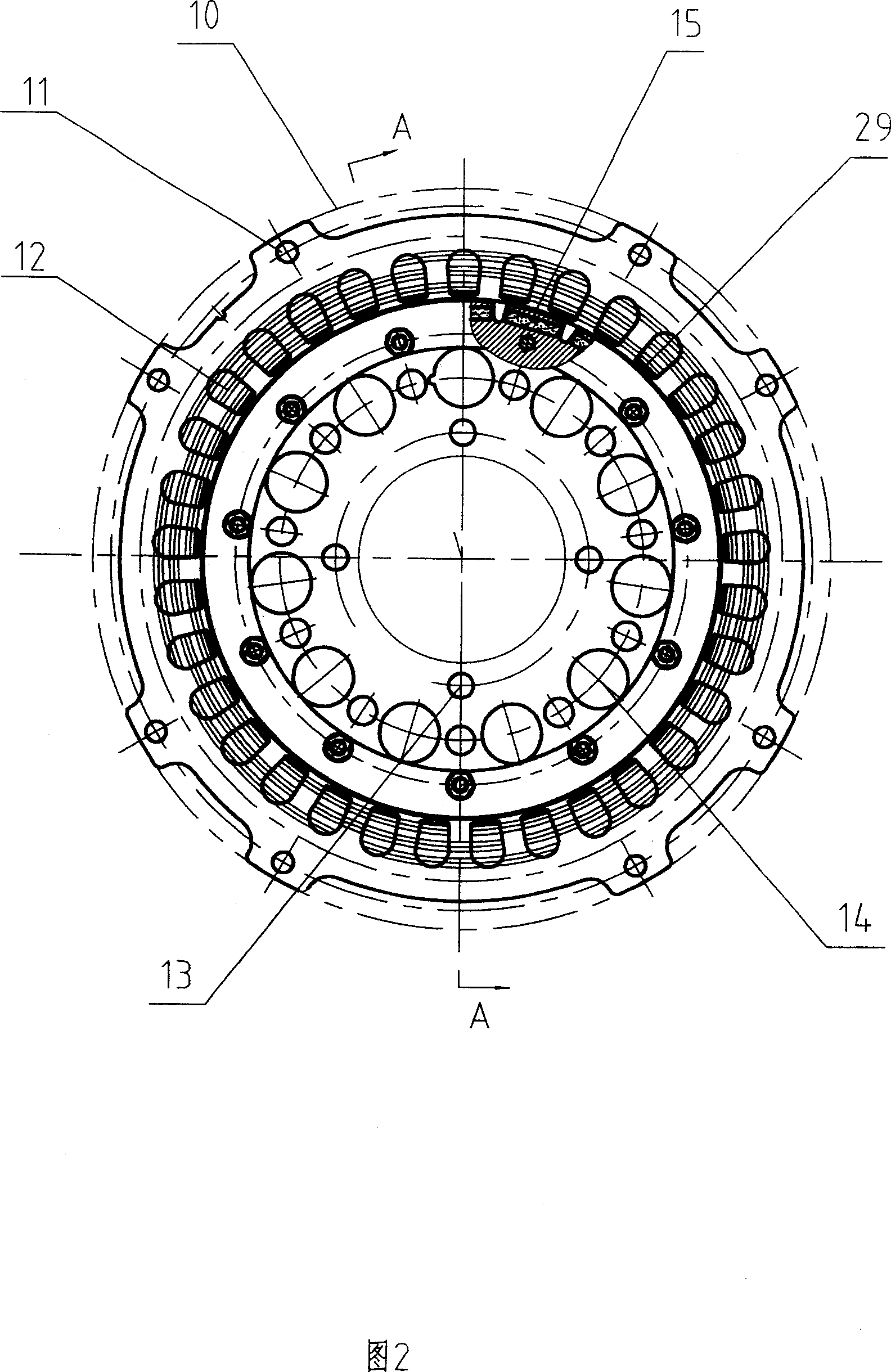
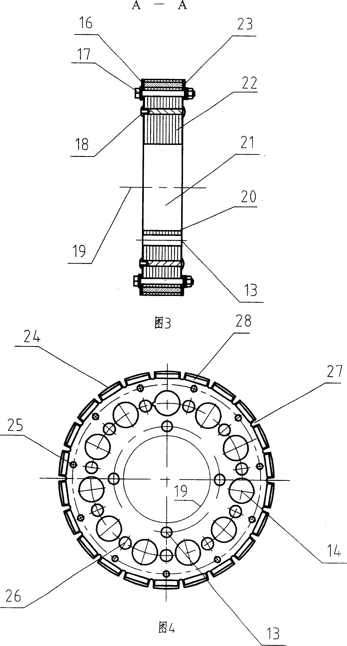
[0021] This embodiment is mainly composed of engine assembly 1, stator seat 2, rotor seat 3, rotor assembly 4, bolt 5, stator assembly 6, bolt 7, stator seat positioning opening 8, rotor seat positioning opening 9, stator positioning circle 10 , stator bolt holes 11, stator windings 12, rotor bolt holes 13, rotor cooling ventilation holes 14, permanent magnets 15, first permanent magnet baffle 16, baffle fixing bolts 17, rivets 18, rotor rotation center 19, positioning inside the rotor Circle 20, rotor body 21, rotor punching plate 22, second permanent magnet baffle plate 23, rotor body circle 24, baffle plate bolt hole 25, rivet hole 26, magnetic resistance groove 27, permanent magnet storage groove 28, insert piece 29 and The rotary body 30 of the engine etc. is composed.

[0022] As shown in Fig. 1 and Fig. 2: the rotor assembly 4 of the present in...


PUM


Abstract

The disclosed rotor of permanent magnet generator is suitable to permanent magnet generator in miniaturization, lightweight, and thin type. The rotor includes punched pieces of rotor, permanent magnets. Characters are that riveting punched pieces of rotor constitutes rotor body where slots for taking in permanent magnets are distributed around circumferencial direction. After taking in permanent magnets, rotor body is fixed on rotary body of generator directly. Structure with no bearing adopted in the invention makes rotor simple and compact farthest so as to save cost, raise service life, realize high output efficiency, and high output power. The invention guarantees that when rotor rotates, rare earth permanent magnet will not fall off, as well as reduces magnetic leakage, raises safety, stability and durability of rotor.

Description

technical field [0001] The invention relates to a rotor of a multi-pole inner rotor type permanent magnet generator, in particular to a rotor which improves structural safety and power generation efficiency, and is suitable for miniaturized, lightweight and thin permanent magnet generators , belongs to the technical field of generators. Background technique [0002] Before the disclosure of the present invention, in the known technology, there are many disclosures about the application of permanent magnet rotors in electric motors. For example, the application number is CN03818684.5, which discloses a rotating electrical machine comprising a stator with multiple coils and The inner side of the stator, the rotor core rotatably supported on the rotating shaft, and a plurality of magnets accommodated in slot holes provided in the rotor core, the circumferential direction of the plurality of magnets constituting one magnetic pole The angle is represented by an electrical angle,...

Claims


Application Information

Patent Timeline
Patent Type & Authority Applications(China)
IPC IPC(8): H02K1/27H02K15/03
CPCH02K1/276
Inventor 肖亨琳
Owner WUXI KIPOR POWER CO LTD
Why Eureka
Try Eureka