Optical logic gate

A technology of optical logic and logic functions, applied in the field of all-optical logic gates, which can solve problems such as response time limitations, high-cost optical fibers, and insufficient performance

Inactive Publication Date: 2007-07-25
TELEFON AB LM ERICSSON (PUBL)
View PDF0 Cites 14 Cited by
  • Summary
  • Abstract
  • Description
  • Claims
  • Application Information

AI Technical Summary

Problems solved by technology

However, in the first example, the response time of semiconductors limits the maximum signal bit rate; meanwhile, in the second example, the performance achievable with commercial optical fibers is insufficient and requires specialized high-cost optical fibers, which are difficult to produce and are not suitable for commercial use.

Method used


Image

  • Optical logic gate
  • Optical logic gate
  • Optical logic gate

Examples


Embodiment Construction

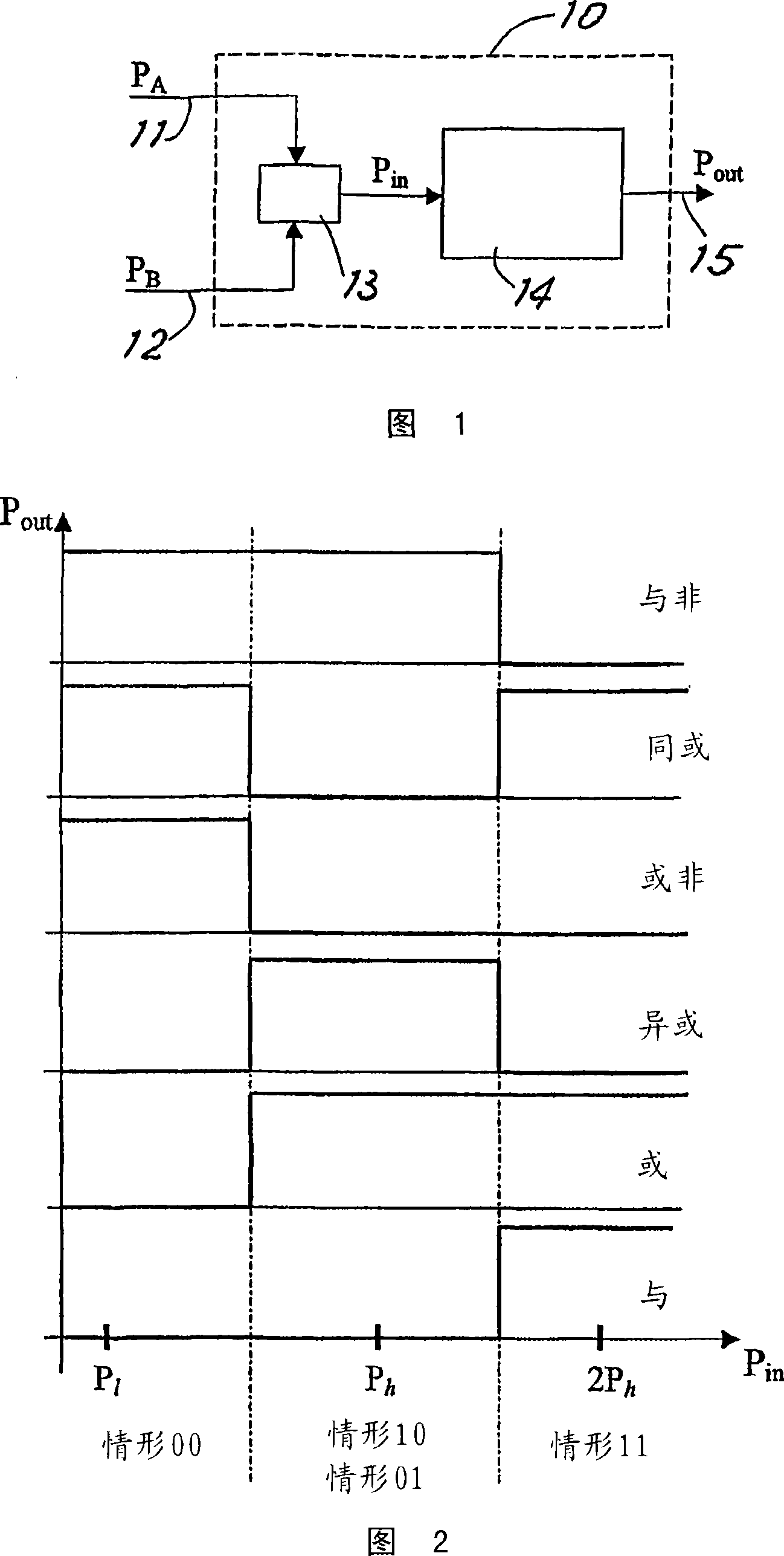
[0021] Referring to Figure 1, there is shown a block schematic diagram of an optical logic gate 10 in accordance with the principles of the present invention. The optical logic gate 10 includes two optical input ports 11 and 12 to which digital optical signals A, B to be subjected to logical operations are applied. The two optical signals A and B are summed by optical combining (power summing) means 13 to give a power P in =P A +P B The optical signal, where P A and P B are the powers of the input signals A and B, respectively. The power P output from the summing device 13 in is applied to a nonlinear optical device 14 with certain nonlinear characteristics, and the optical output port 15 of the nonlinear optical device 14 is an output port of a logic gate.

[0022] Essentially, when the input power P into the nonlinear module in When is the sum of the power of the two digital signals A and B, the output power P from the nonlinear module out Able to represent the logic...


PUM


Abstract

An optical logic gate (10) comprises the following components: a first and a second light input ends (11 and 12) which are used for receiving the respective light signals (A and B), and a output end (15) which is used for outputting the optical signal (Pout) that represents the result applied with the necessary logical function. The logic gate is characterized by the light combining device (13) which is used for combining the light signals for generating the corresponding combined signal, the power (Pi) of the combined signal is the combination of the optical signal powers (PA and PB), and the non-linear optical device (14) which is used for receiving the combined signal (Pi) and emitting the optical output signal (Pout). The logical function depends on the characteristic of the non-linear optical device, and the characteristic is selected that the power of the output signal is relevant to the power of the combined signal through the selected logic function.

Description

technical field [0001] The present invention relates to optical logic gates, more particularly all-optical logic gates, which are reconfigurable (in terms of logic function) and advantageously also reproducible. Throughout this application, all-optical means performing logical operations in the optical domain without conversion into corresponding electrical quantities. Background technique [0002] In the field of fiber optic communications, the ability to perform ultrafast logic operations on optical signals without converting them back to electrical signals has long been desired. [0003] For example, broadband packet-switched networks require ultrafast all-optical signal processing in order to perform high-speed routing functions such as packet synchronization, address recognition, and real-time content parsing. To realize these functions, the application of all-optical digital logic gates seems essential. Logic gates should have high contrast between "on" and "off" sta...

Claims


Application Information

Patent Timeline
Patent Type & Authority Applications(China)
IPC IPC(8): G02F3/00G02F1/35
CPCG02F1/3519G02F3/00
Inventor A·博戈尼P·赫尔菲L·波蒂F·蓬齐尼
Owner TELEFON AB LM ERICSSON (PUBL)
Why Eureka
Try Eureka