Exchanger with honeycomb structure

A technology of honeycomb structure and exchanger, which is applied in the direction of heat exchange equipment, heat exchanger type, indirect heat exchanger, etc. It can solve the problems of difficult placement of testing instruments, long production cycle, and large waste of materials, so as to save internal assembly, Excellent mechanical properties and great operational flexibility

A technology of honeycomb structure and exchanger, which is applied in the direction of heat exchange equipment, heat exchanger type, indirect heat exchanger, etc. It can solve the problems of difficult placement of testing instruments, long production cycle, and large waste of materials, so as to save internal assembly, Excellent mechanical properties and great operational flexibility

CN101008557AInactive Publication Date: 2007-08-01SOUTH CHINA UNIV OF TECH

Image

  • Exchanger with honeycomb structure
  • Exchanger with honeycomb structure

Examples


Embodiment Construction

[0028] The present invention will be described in further detail below with reference to the accompanying drawings and examples, but the embodiments of the present invention are not limited thereto.

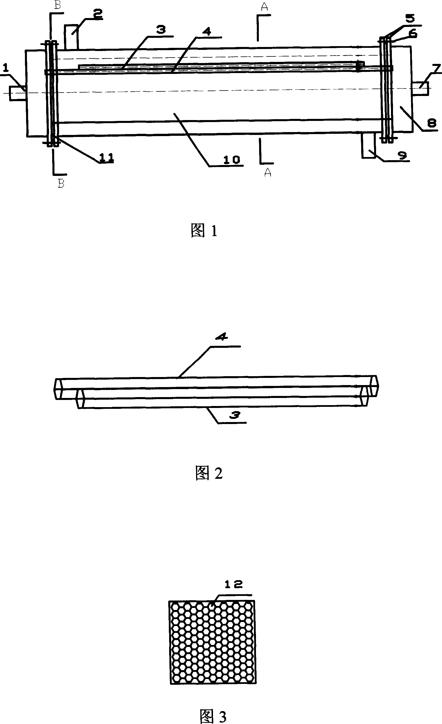
[0029] As shown in Figure 1, a kind of exchanger with honeycomb structure comprises casing 10 and tube bundle, and casing 10 is provided with fluid inlet 2 and fluid outlet 9, and casing 10 two ends are respectively provided with tube box 8, and tube box 8 is provided with a tube bundle fluid inlet 7 and an outlet 1, and the housing 10 has a regular hexagonal cross-sectional shape. The tube bundle consists of a plurality of short honeycomb tube bundles 3 and long honeycomb tube bundles 4 to form a honeycomb tube bundle core 12, and the gap between the outer edge of the honeycomb tube bundle core 12 and the shell 10 is less than 3mm. Both ends of the long honeycomb tube bundle 4 communicate with the inlet 7 and the outlet 1 in the tube box 8 respectively.

[0030] As shown in Fig...


PUM


Abstract

The invention discloses an exchanger with honeycomb structure, wherein, its frame (10) is in regular hexagon shape; the tube beam has several short honeycomb tubes (3) and long honeycomb tubes (4) to form honeycomb tube element (1), while the long honeycomb tubes (4) are adjacent with the short ones (3) with shared walls; the thickness of the wall of long and short tubes (4, 3) is 0.2-2mm; two ends of long honeycomb tube (4) are through to the inlet (7) and the outlet (1) of tube box (8). The invention has large unit heat exchange area, compact structure, high factor K, and high flexibility.

Description

technical field [0001] The invention relates to a shell-and-tube heat exchanger in energy technology, in particular to an exchanger with a honeycomb structure. Background technique [0002] Heat exchanger is a general process equipment widely used in power, metallurgy, refrigeration, oil refining, chemical industry, aviation, atomic energy, medicine and other industrial sectors. With the increasingly prominent energy problems, it is required to reduce the volume of the equipment as much as possible under the premise of satisfying the heat exchange, that is, to improve the compactness of the equipment, thereby reducing the weight of the equipment, saving materials, and correspondingly reducing the occupied area. As a result, high-efficiency heat exchangers came into being. In some application fields, there are special requirements for the size and weight of heat exchange equipment. Therefore, ultra-compact heat exchangers with small volume and large heat exchange area per un...

Claims


Application Information

Patent Timeline
01 Aug 2007
Publication
CN101008557A
IPC
F28D1/02; F28D1/04; F28F1/04
Inventors
ๆŽ้™; ้—ซๅ†›ๅจ