Supercharge Your Innovation With Domain-Expert AI Agents!

Liquid dispensing method and system with headspace gas removal

A gas and liquid technology, applied in the field of storage and distribution systems, can solve the problem of difficult control of the gas volume in empty detection

Inactive Publication Date: 2007-08-01
先科材料有限公司
View PDF1 Cites 8 Cited by
  • Summary
  • Abstract
  • Description
  • Claims
  • Application Information

AI Technical Summary

Problems solved by technology

In traditional systems, the amount of empty test gas remaining in the container is not easily controlled

Method used


Image

  • Liquid dispensing method and system with headspace gas removal
  • Liquid dispensing method and system with headspace gas removal

Examples


Embodiment Construction

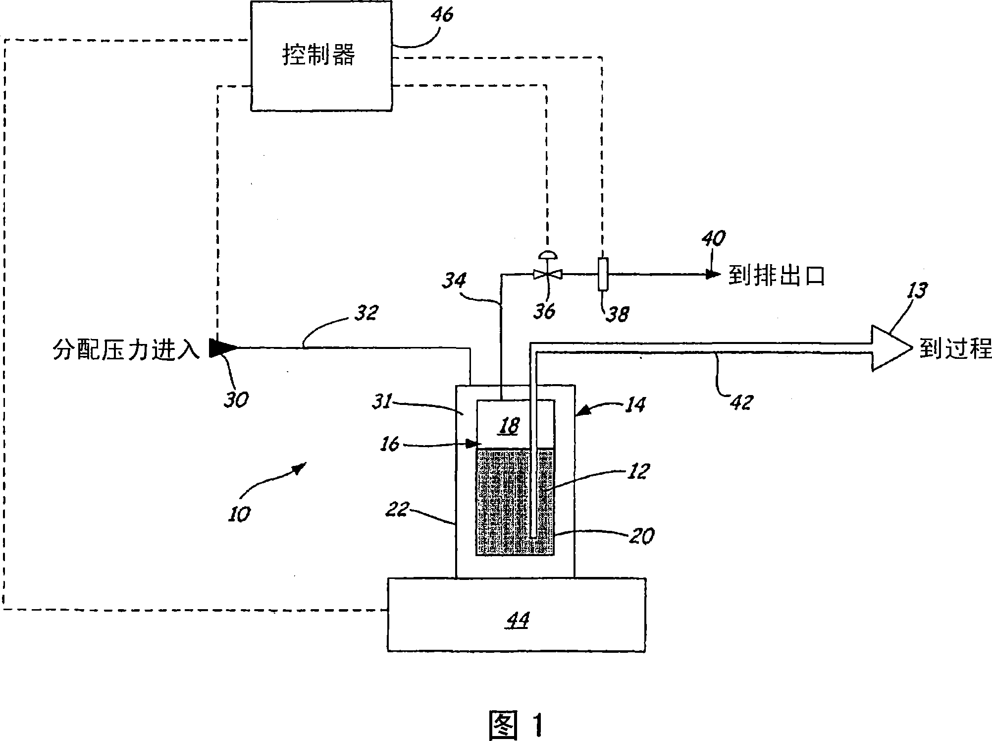
[0012] 1 is a schematic diagram of a system 10 for dispensing a liquid 12 from a container 14 including a headspace 16 filled with a headspace gas 18 to a manufacturing process 13 in accordance with a preferred embodiment of the present invention. Container 16 includes a flexible inner container 20 and a rigid outer container 22 . System 10 further includes compressed air or nitrogen supply 30, compressed air passage 32, headspace gas passage 34, discharge valve 36, liquid sensor 38, headspace gas discharge 40, flow passage 42, vessel scale 44 and system controller 46 .

[0013] The compressed air source 30 is connected to the compressed space 31 (ie, the space between the inner wall of the outer container 22 and the outer surface of the inner container 20 ) through a compressed air passage 32 . The interior of the inner container 20 is connected to a headspace gas outlet 40 through a gas passage 34 . A discharge valve 36 and a liquid sensor 38 are connected along the gas pa...


PUM


Abstract

A liquid dispensing method and system for dispensing from a container including an outer container and an inner container, a portion of the inner container occupied by the liquid, a remainder of the inner container occupied by a headspace gas. The system includes a probe having a flow passage therein and a gas passage communicating between the interior of the inner container and an exterior of the outer container. Fluid (such as air or nitrogen) is caused to flow under pressure into a space between inner walls of the outer container and the inner container to force the headspace gas out of the inner container via the gas passage and to force liquid out of the inner container through the flow passage in the probe to a manufactuaring process.

Description

technical field [0001] The present invention relates to a storage and dispensing system for the storage and dispensing of liquids. More specifically, the present invention relates to a method and system for dispensing liquid from a container containing a headroom gas to a manufacturing process. Background technique [0002] Certain manufacturing processes require the use of liquid chemicals such as acids, solvents, bases, photoresists, dopant, inorganic solutions, organic solutions, biological solutions, pharmaceuticals, and radioactive chemicals. The storage and distribution system allows the use of selectable containers to dispense liquid chemicals to the manufacturing process at specified times. These process liquids are usually dispensed from pressurized storage and dispensing containers by special dispensing pumps. [0003] After filling these containers at the filling facility, the containers are typically shipped to a location for use in the manufacturing process. ...

Claims


Application Information

Patent Timeline
Patent Type & Authority Applications(China)
IPC IPC(8): B65D83/00B67D1/08B67D5/08B67D5/42B67D7/02B67D7/08B67D7/60
CPCB67D7/0261B65D83/00
Inventor 凯文·T·欧多尔蒂拉塞尔·F·奥伯芝约瑟夫·P·门宁格雷戈里·B·诶登唐纳德·C·格兰特
Owner 先科材料有限公司
Features
  • R&D
  • Intellectual Property
  • Life Sciences
  • Materials
  • Tech Scout
  • Unparalleled Data Quality
  • Higher Quality Content
  • 60% Fewer Hallucinations
Learn More