Process for the manufacture of chlorodifluoromethane

A production method and condenser technology, applied in the field of preparation of chlorodifluoromethane

Inactive Publication Date: 2007-08-01
EI DU PONT DE NEMOURS & CO
View PDF0 Cites 4 Cited by
  • Summary
  • Abstract
  • Description
  • Claims
  • Application Information

AI Technical Summary

Problems solved by technology

CHCl leaving the condenser 2 F is problematic because it is similar to CHClF in volatility 2 , and will spend most of the separation with CHClF 2 together

Method used


Image

  • Process for the manufacture of chlorodifluoromethane
  • Process for the manufacture of chlorodifluoromethane
  • Process for the manufacture of chlorodifluoromethane

Examples


Embodiment 1

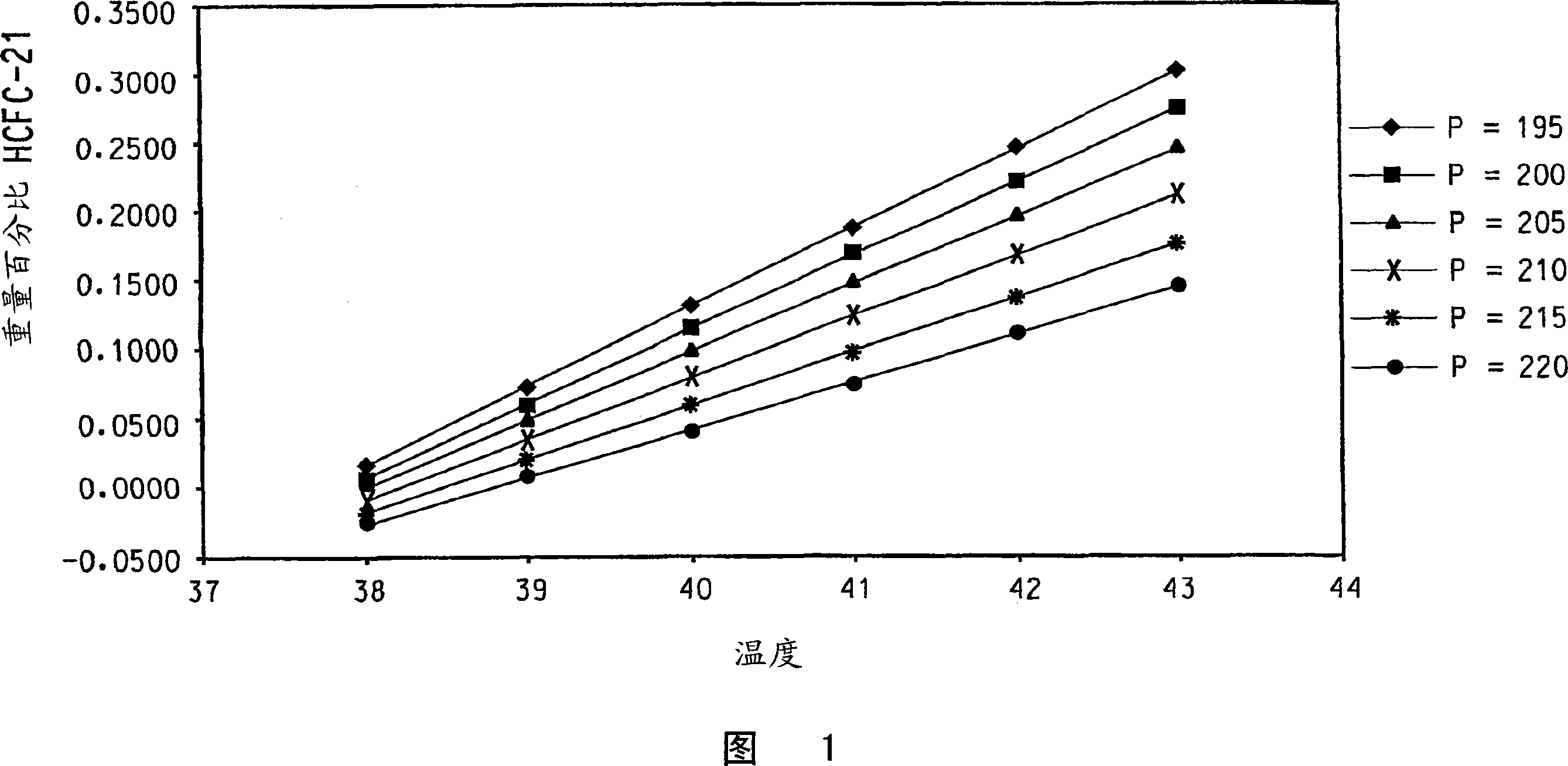
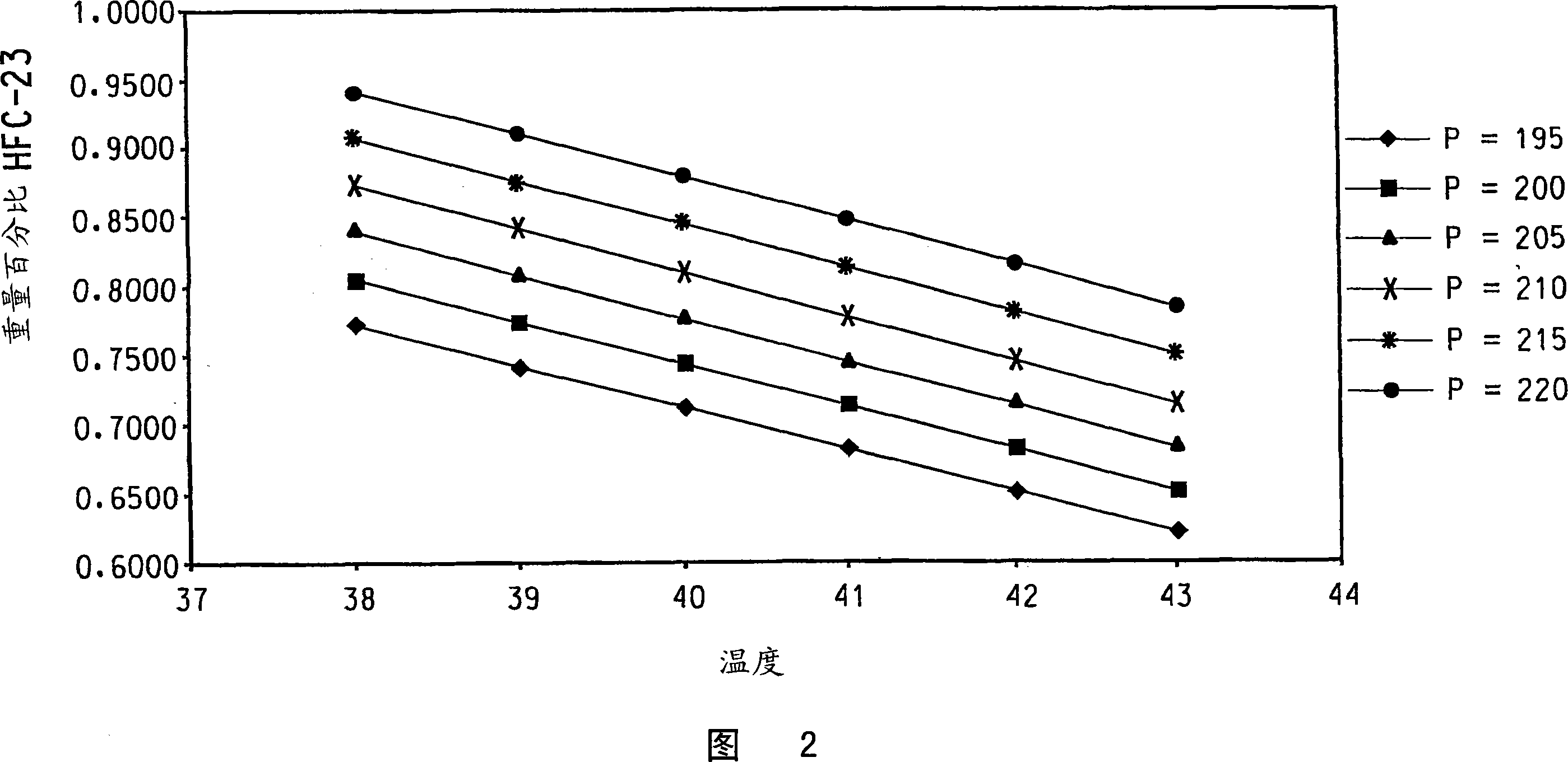
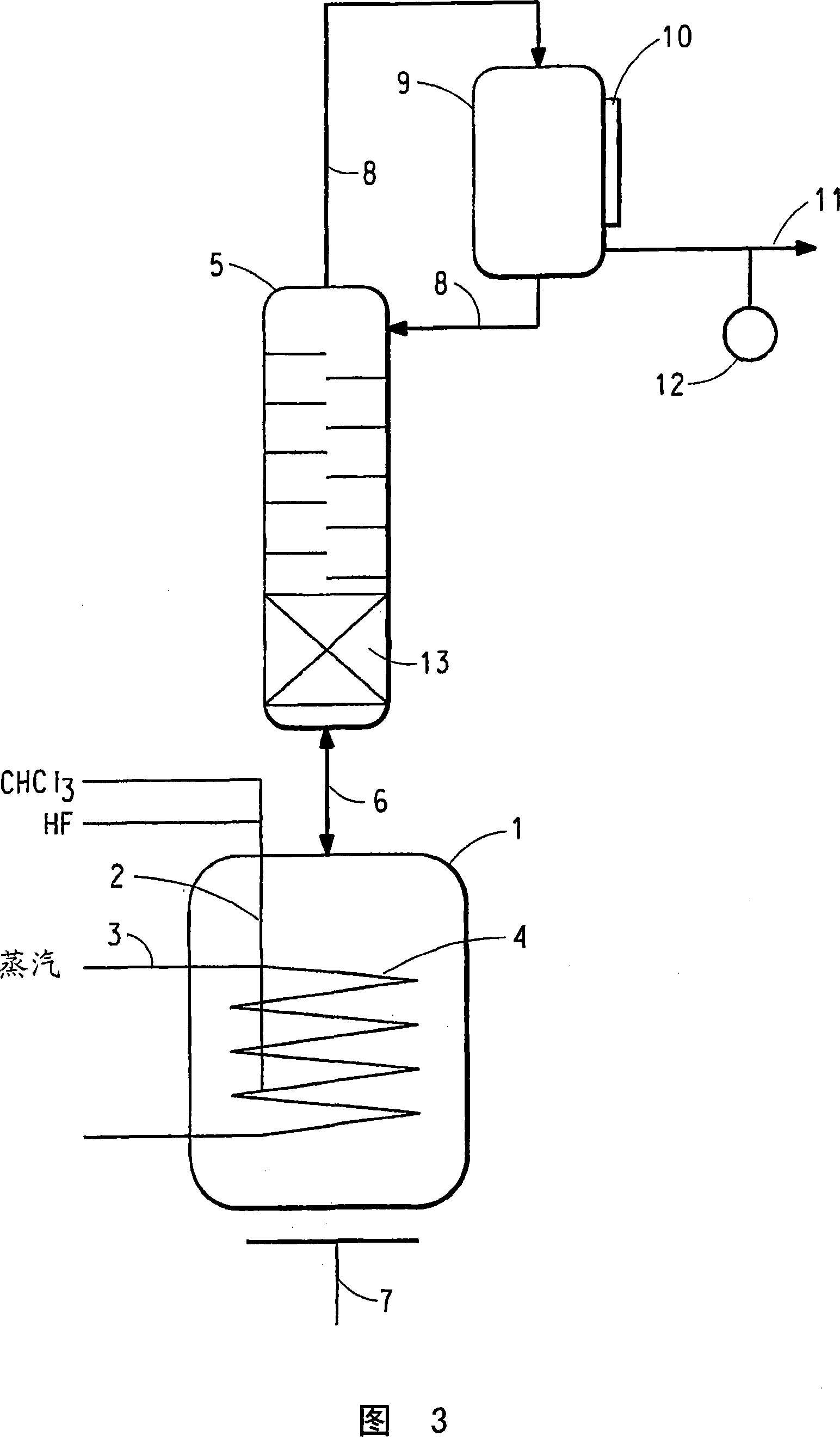
[0070]The reaction apparatus and procedure of Comparative Example 1 were used in this example with the following changes. The reactor liquid phase is maintained at the maximum mass that does not cause entrainment and / or flooding of the reactor liquid phase into the reflux column 5 . A brine cooling medium is circulated through the cooling jacket 10 of the condenser 9 and is used to set the reflux ratio of the condenser 9 to be substantially constant during steady state operation of the reactor so that part of the reflux column vapor effluent condenses and forms 2 of the condenser liquid effluent, and have reduced or substantially no CHCl 2 F and CHF 3 containing CHClF 2 and HCl in the condenser vapor effluent. The reflux ratio averaged 1.60 (min 1.41, max 1.79). The temperature of a point within the lower 1 / 3 of the theoretical stage of the reflux column is 41.5°C on average (minimum 37.9°C, maximum 43.4°C). The amount of pentavalent antimony catalyst present in the liqui...

Embodiment 2

[0077] The reaction apparatus and procedure of Example 1 were used in this example with the following changes. The reflux column of Example 1 was replaced with a cylindrical column of the same dimensions, however, the bottom 1 / 3 of the length of the reflux column contained a packed bed of stainless steel #25 IMTP packed packing (from Norton Chemical Process Products Co., Ohio, USA), The top 2 / 3 of the reflux column contained 18 trays and had no packing. The average reflux ratio was 1.59 (minimum 1.53, maximum 1.99). The temperature of a point within the lower 1 / 3 of the theoretical stage of the reflux column is 45.9°C on average (minimum 36.5°C, maximum 48.7°C). The amount of pentavalent antimony catalyst present in the liquid phase of the reactor averaged 28.4 wt% (minimum 27.6 wt%, maximum 29.2 wt%). CHCl via line 2 to the reactor 3 The / HF feed ratio averaged 2.78 (min 1.71, max 2.95). Reactor pressure measured at the upper end of the reflux column averaged 199.8 psig (...


PUM


Abstract

A process is disclosed for the manufacture of CHClF2which involves contacting CHCl3, HF and pentavalent antimony catalyst in the liquid phase; passing reactor vapor effluent to a reflux column to produce a reflux column vapor effluent of CHClF2 and HCl; passing the reflux column vapor effluent to a condenser to produce a condenser liquid effluent of CHClF2 and a condenser vapor effluent of CHClF2 and HCl; passing the condenser liquid effluent to the reflux column upper end; and recovering CHClF2 from the condenser vapor effluent. The concentration of CHCl2F and CHF3 in the condenser vapor effluent is controlled by: (i) controlling the temperature at a point within the lower third of the theoretical stages of the reflux column by controlling the heat input to the reactor liquid phase; (ii) controlling the pressure in the reactor, reflux column and condenser by controlling the rate at which the condenser vapor effluent is removed from the condenser; (iii) maintaining the reflux ratio of the condenser at a substantially constant value; and (iv) maintaining the reactor liquid phase at substantially the maximum mass that does not result in entrainment or flooding of the reflux column. Also disclosed is CHClF2 which is a product of this process. Also disclosed is a refrigerant comprising CHClF2 and a method for its manufacture, a polymer foam blowing blend comprising CHClF2 and a method for its manufacture, fluoromonomers tetrafluoroethylene and hexafluoropropylene produced by using CHClF2 and a method for their manufacture, and a fluoropolymer produced by using CHClF2 as a fluoromonomer precursor and a method for its manufacture; all involving the manufacture of CHClF2 in accordance with the above process.

Description

field of invention [0001] The present invention relates generally to a process for the production of chlorodifluoromethane, and more particularly to a process for the production of chlorodifluoromethane in which unwanted dichlorofluoromethane and trichlorodifluoromethane in the chlorodifluoromethane are controlled through the use of certain process parameters The concentration of fluoromethane. Background technique [0002] Trifluoromethane (HFC-23, CHF 3 ) in chlorodifluoromethane (HCFC-22, CHClF 2 ) as an unwanted by-product in the preparation. CHF 3 With a global warming potential of 11,700 over a 100-year time frame, its potential impact on climate change is significant. Within the category of hydrofluorocarbons (HFCs), perfluorocarbons (PFCs) and SF6, CHF 3 It is said to be the second largest contributor to greenhouse gas emissions in the United States. [0003] CHClF 2 Produced in several developed and developing countries and used as a refrigerant, as a mixing ...

Claims


Application Information

Patent Timeline
Patent Type & Authority Applications(China)
IPC IPC(8): C07C17/20C07C19/08C07C17/269C07C21/185B01J23/18
CPCC07C19/10B01J35/12C07C17/206B01J23/18C09K5/044B01J27/08Y02P20/40
Inventor M·J·克里斯特马斯Y·N·迪米特拉托斯
Owner EI DU PONT DE NEMOURS & CO
Why Eureka
Try Eureka