
Voltage source converter

A voltage source converter and converter technology, which is applied to output power conversion devices, electrical components, and AC power input to DC power output, etc., can solve the problem of high cost of filtering equipment, avoid control instability, reduce Hardware performance requirements, cost reduction effects

Inactive Publication Date: 2007-08-01
ABB (SCHWEIZ) AG
View PDF2 Cites 4 Cited by
  • Summary
  • Abstract
  • Description
  • Claims
  • Application Information

AI Technical Summary

Problems solved by technology

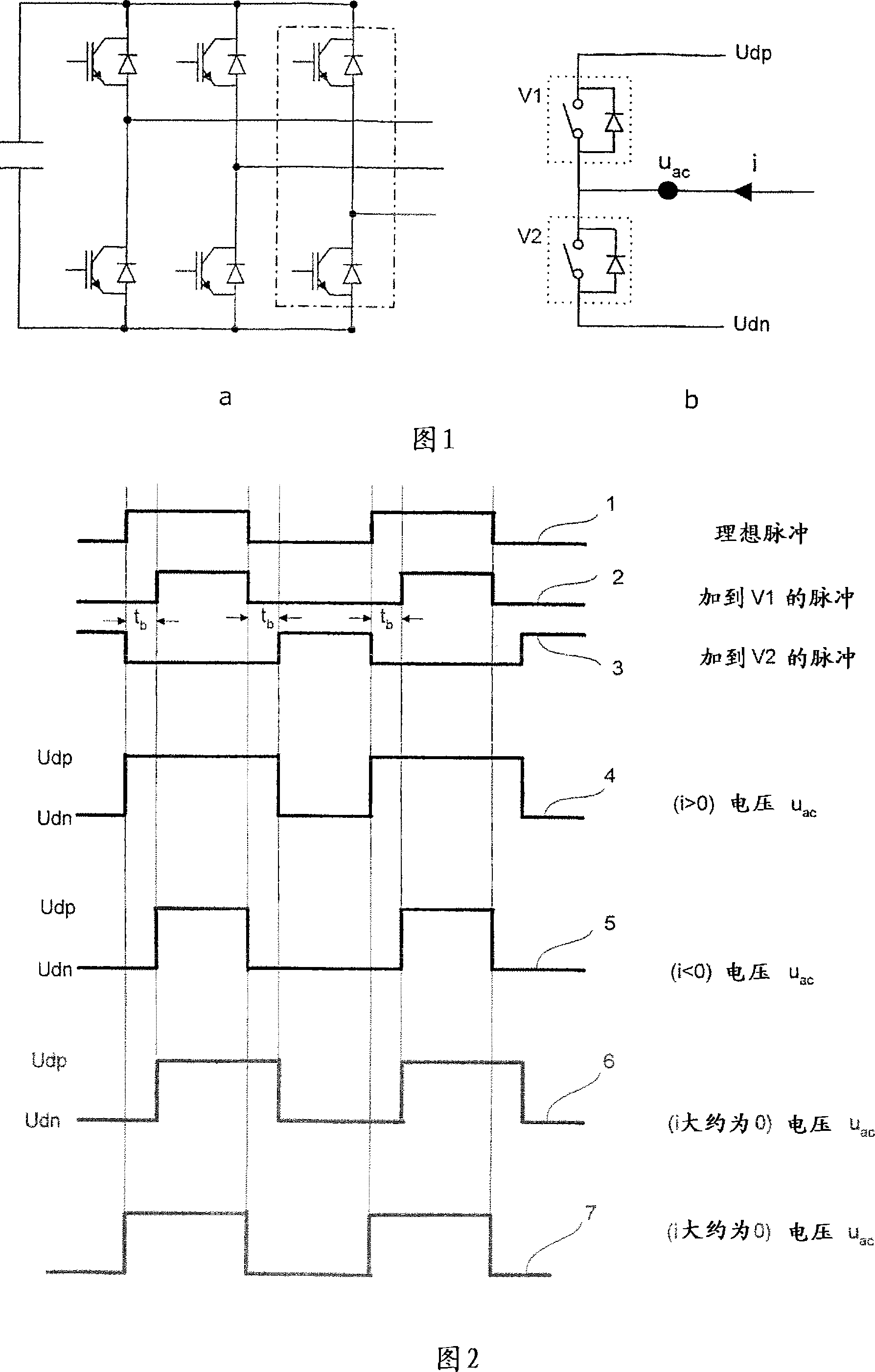
[0009] The second reason is the blanking time, or "dead time", which must be inserted between the open (close) command of the first valve on the same bridge and the close (open) command of the second valve
However, it is difficult to guarantee the correctness of the predicted current, because the correctness of the predicted current not only depends on the accuracy of the converter reference voltage, measured current and measured voltage, but also depends on the calculation of the control process speed
[0018] In high power applications such as HVDC and STATCOM, low harmonics lead to very high cost of filtering equipment

Method used


Image

  • Voltage source converter
  • Voltage source converter
  • Voltage source converter

Examples


Embodiment Construction

[0043] A two-stage converter bridge is shown in Figure 1 as an example. Figure 1a depicts a full three-phase forced commutation bridge and Figure 1b is a one-phase portion of the bridge. The bridge section includes a first valve V1 and a second valve V2, and has a lower DC terminal U dn and on the DC terminal U dp . Each valve comprises at least one switching device comprising a self-commutated semiconductor element and a diode element connected in antiparallel therewith. In the embodiment shown self-commutating semiconductor elements comprise IGBTs. The bridge has an AC terminal U with an AC current i ac .

[0044] When operating the converter, a blanking time, or "dead time," must be inserted between the command to open (close) the first valve and the command to close (open) the second valve, or vice versa. This is because both valves of the converter bridge should never be closed at the same time, thus preventing a short circuit. The effect of blanking time is shown ...


PUM


Abstract

An apparatus for controlling a voltage source converter with at least two bridges V1, V2 of semiconducting self commutating elements 11 connected in anti-parallel with a diode 12, comprising means OPWM for producing a switching control pulse train 19 to form a fundamental frequency18, means C for effecting a switching order CP and means VCU for detecting a switching event.

Description

technical field [0001] The invention relates to a voltage source converter (VSC) comprising a plurality of self-excited commutated semiconductor elements. More precisely, the invention relates to a method and a device for controlling a VSC by means of a modulated signal, such as a pulse width modulated (PWM) signal. In particular, the invention relates to a VSC comprising a plurality of semiconductor elements connected in series, and in particular to a converter station for a high voltage direct current (HVDC) transmission line comprising such a VSC. [0002] The PWM-controlled converter described herein includes an inverter and a rectifier. Such converters can be used in low power applications such as motor drive systems, as well as high power applications such as high voltage direct current (HVDC) transmission systems and static var compensator (STATCOM) systems. Background technique [0003] A converter, more precisely a voltage source converter, provides electrical cou...

Claims


Application Information

Patent Timeline
Patent Type & Authority Applications(China)
IPC IPC(8): H02M1/12H02MH02M7/5387
CPCH02M7/53873H02M1/12
Inventor 罗兰·西耶斯特伦江英拉尔斯·多夫内斯
Owner ABB (SCHWEIZ) AG
Learn More