
Method for fabricating highly effective generator and highly effective generator

A manufacturing method and generator technology are applied in the manufacture of stator/rotor body, magnetic circuit shape/style/structure, magnetic circuit rotating parts, etc. Efficiency, drag reduction, ease of manufacture and installation

Inactive Publication Date: 2011-01-12
石为民
View PDF0 Cites 0 Cited by
  • Summary
  • Abstract
  • Description
  • Claims
  • Application Information

AI Technical Summary

Problems solved by technology

[0002] The electromechanical energy conversion efficiency of existing generators is notoriously low

Method used


Image

  • Method for fabricating highly effective generator and highly effective generator
  • Method for fabricating highly effective generator and highly effective generator
  • Method for fabricating highly effective generator and highly effective generator

Examples


Embodiment 1

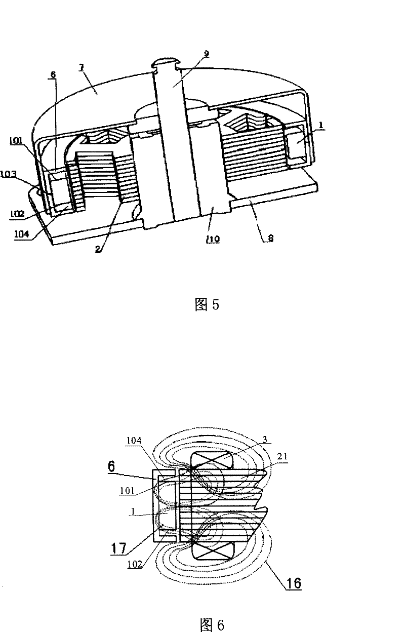
[0025] Embodiment 1, a high-efficiency generator and its manufacturing method, such as Figure 5 Shown is right figure 1 Schematic diagram of the structure of the shown generator after partial improvement. The improvement is that a shielding ring 6 is fixed on the upper and lower sides and the back side 103 of the ring-shaped permanent magnet 1, and the axial section of the shielding ring 6 along the central axis has a "]"-shaped structure. The axial distance is equal to the axial thickness of the iron core of the winding wire package, wherein there is a gap 104 between the upper and lower sides (101, 102) of the permanent magnet 1 and the shielding ring 6, so that the magnetic force lines of the rotating magnetic field enter The iron core 2 is lower than the thickness of the iron core 2. The shielding ring 6 must be made of magnetically permeable materials such as iron or ferrite. other structures with figure 1 The existing structure shown is identical. Figure 6 A schem...


PUM


Abstract

The invention relates to one motor process method, which sets shield ring on side of the rotation magnetic field side with same width to iron core thickness. The invention also discloses one motor by above method to improve motor output power and energy conversion efficiency.

Description

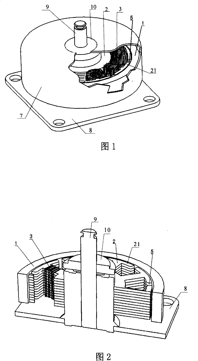
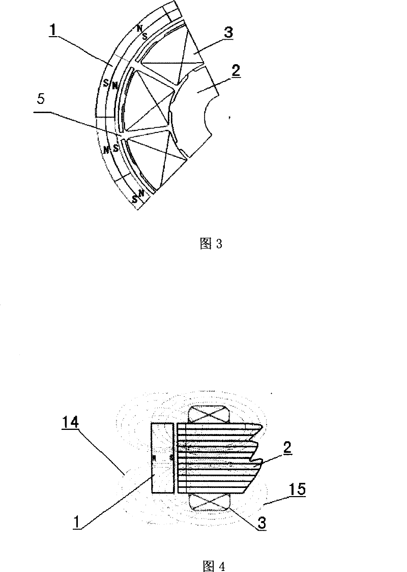
technical field [0001] The invention relates to a manufacturing method of a generator for improving the energy conversion efficiency of the generator and a generator manufactured by the method. Background technique [0002] The electromechanical energy conversion efficiency of existing generators is notoriously low. One of the important reasons is that when the generator outputs current, each coil winding will generate a magnetic field, and the circulation direction of the magnetic force lines of the magnetic field is exactly on the same plane as the moving direction of the magnetic force lines of the rotating magnetic field. The magnetic force lines of the wire-wrapped magnetic field and the magnetic force lines of the rotating magnetic field conflict with each other and directly hinder the rotational movement of the rotating magnetic field. figure 1 , figure 2 What is shown is a schematic diagram of mutual interference between the existing generator rotating magnetic fi...

Claims


Application Information

Patent Timeline
Patent Type & Authority Patents(China)
IPC IPC(8): H02K15/03H02K1/27
Inventor 石为民
Owner 石为民
Learn More