
Method for control of a pressurised air supply system for a motor vehicle

A technology of compressed air and supply system, applied in the direction of pump/compressor arrangement, etc., can solve the problems of motor vehicle speed loss, air compressor power consumption not being targeted to save energy, low motor vehicle speed, etc.

Inactive Publication Date: 2007-08-15
VOITH TURBO GMBH & CO KG
View PDF0 Cites 5 Cited by
  • Summary
  • Abstract
  • Description
  • Claims
  • Application Information

AI Technical Summary

Problems solved by technology

Due to the fixed presetting of the two boundary values, it can happen that the vehicle is just driving on a steep uphill road, despite the full power output of the drive engine, resulting in a very low vehicle speed and at the same time the pressure in the compressed air system The pressure drops below the minimum value due to the connected air consumer, which activates the air compressor
Since the air compressor is also driven by the drive engine of the motor vehicle, the necessary power consumption of the air compressor is no longer available for driving the motor vehicle, and the speed of the motor vehicle is further lost
[0005] On the other hand, the power consumption of the air compressor has hitherto not been used in a targeted and energy-efficient manner due to the preset, constant limit values ​​for switching the air compressor on and off.

Method used


Image

  • Method for control of a pressurised air supply system for a motor vehicle
  • Method for control of a pressurised air supply system for a motor vehicle

Examples


Embodiment Construction

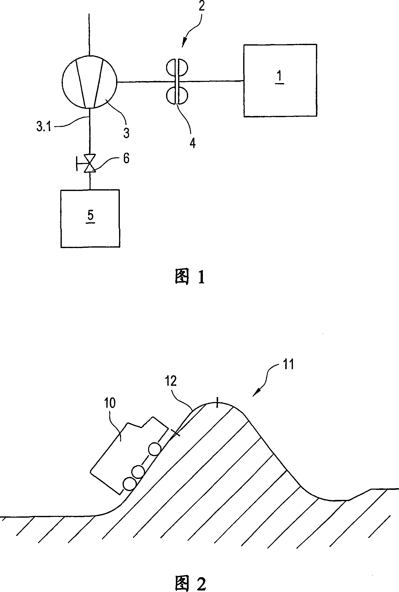
[0021] Fig. 1 shows the driving engine 1 of the motor vehicle, the driving engine is connected to the transmission connecting device connected to the air compressor 3 by filling the hydraulic coupling 4 with the working medium, especially the oil in the engine circulation oil circuit 2 in. When the engine 1 drives the air compressor 3 , that is to say when the method according to the invention is switched to the supply state, the air compressor supplies air to the compressed air system 5 of the motor vehicle via its air output side 3 .

[0022] A switchable and / or adjustable throttle valve 6 is installed in the line for supplying compressed air on the air output side 3.1, ie in the line connecting the air compressor 3 to the compressed air system 5 in an air-conducting manner. . According to an advantageous embodiment of the method according to the invention, when it is desired to transmit as much drive power as possible from the drive engine 1 to the air compressor 3 in the ...


PUM


Abstract

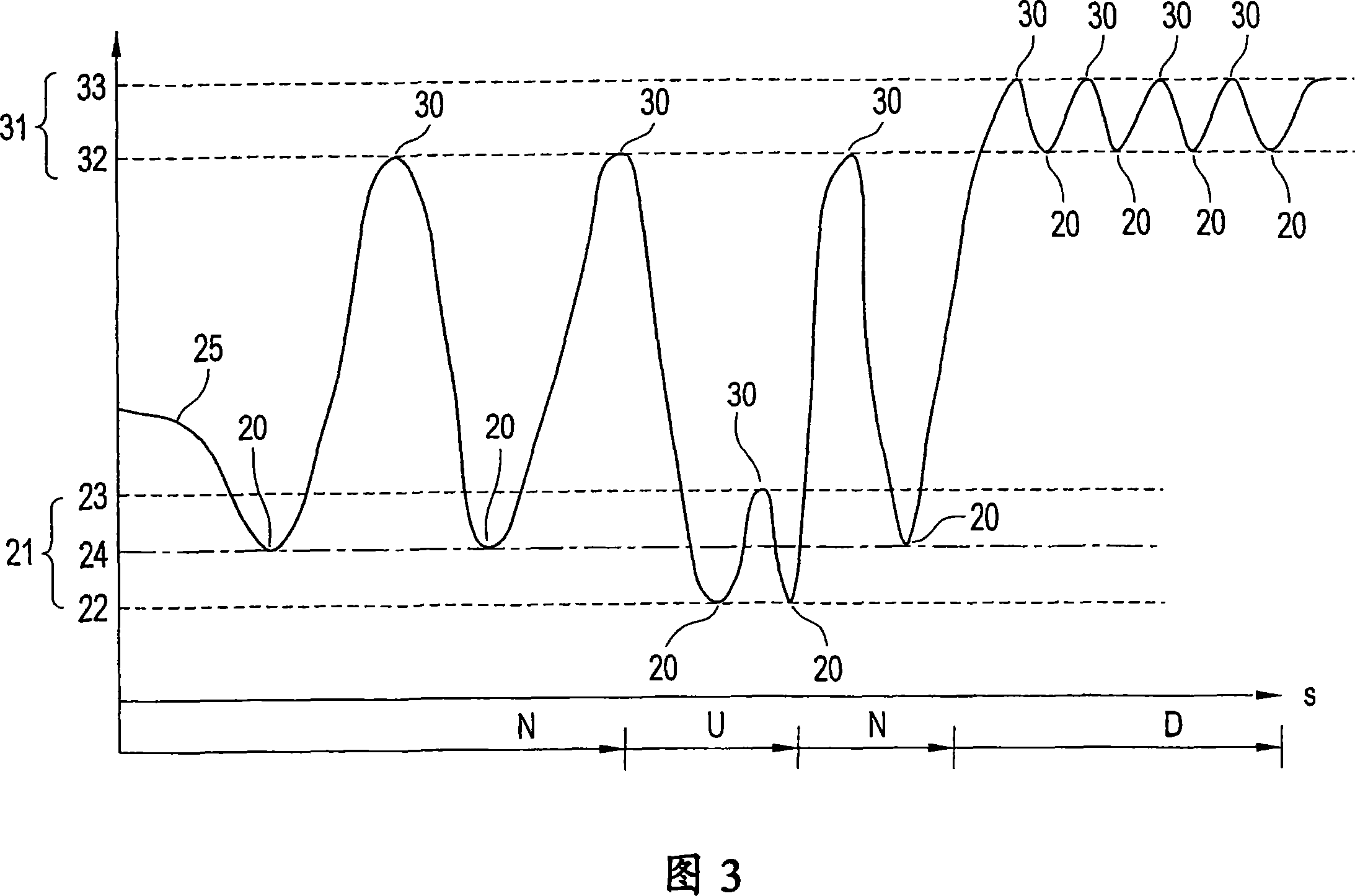
The invention relates to a method for control of a pressurised air supply system for a motor vehicle (10), said system comprising a drive motor (1) for driving the motor vehicle, which drives an air compressor (3) by means of a drive connection (2), or said drive connection for driving the air compressor may be switched on. Said method comprises the following method steps: in a supply condition, the air compressor is driven by the drive motor and connected with the air supply side (3.1) thereof to a compressed air system (5) of the motor vehicle (10), such that compressed air is supplied to the compressed air system, in a non-supply condition, the air compressor is not driven and / or is not connected to the compressed air system, whereby the switching of the supply or non-supply condition is carried out on the basis of a comparison of at least one switch pressure value with a pressure (25) in the compressed air system (5) and the topography of the stretch of road (11) on which the motor vehicle (10) is travelling is recorded, said topography includes the profile of the path (12) which the vehicle (10) must cover within a directly following period of time and / or path distance to a given destination. At least one switch pressure value (20,30) is fixed on the basis of the determined topography.

Description

technical field [0001] The invention relates to a method for regulating a compressed air supply system of a motor vehicle, wherein the system comprises: a drive motor, the drive motor being a motor vehicle drive motor, that is to say, the drive motor being used to propel the motor vehicle forward; It includes an air compressor, which supplies air to a compressed air system of the motor vehicle, and in particular a fluid coupling, which is inserted into a transmission connection between the drive engine and the air compressor. Here the fluid coupling can be filled and emptied, thus switching the air compressor on and off depending on the pressure state in the compressed air system. The air compressor is designed in particular as a piston air compressor. Background technique [0002] The compressed air supply system according to the invention has the advantage that, on the one hand, by "simply" emptying the liquid Force coupling, it is possible to turn off the air compressor...

Claims


Application Information

Patent Timeline
IPC IPC(8): B60T17/02
CPCB60T17/02
Inventor 马库斯·克莱海因茨·赫勒克劳斯·福格尔桑赖因霍尔德·皮蒂乌斯库尔特·阿德勒夫维尔纳·亚当斯
Owner VOITH TURBO GMBH & CO KG
Learn More