Floating roadbed

A floating track bed and floating slab technology, applied in the directions of roads, tracks, ballast layers, etc., can solve the problems of increased vibration and noise, low lateral stiffness, and increased vibration of floating slabs, and can suppress structural vibration and noise. , Improve system stability and improve the effect of structural damping

Active Publication Date: 2010-07-21
GERB QINGDAO VIBRATION CONTROL +1
View PDF2 Cites 4 Cited by
  • Summary
  • Abstract
  • Description
  • Claims
  • Application Information

AI Technical Summary

Problems solved by technology

The rubber floating slab has the following disadvantages: the rigidity of each direction of the rubber bearing block or the laminated steel plate rubber bearing block is mutually restricted, and the transverse stiffness is low, which cannot meet the lateral stability requirements of the ballast bed. Therefore, in addition to the vertically supported rubber bearing The rubber support block for lateral support has a complex structure; the rubber support block is hidden under the floating plate, which is difficult to level, repair and replace, especially from the side or top of the floating track bed; the length of the floating plate is limited, and it is easy to Resonance, plus the damping of the rubber itself is too small to absorb the vibration energy of the floating plate, resulting in increased vibration of the floating plate, significantly increased vibration and noise in the vehicle in the vibration isolation section of the rubber floating plate, and intensified rail friction; rubber on materials and High technological requirements, easy aging, and limited service life, the replacement of rubber support blocks has a great impact on train operation and public travel
[0006] For higher vibration reduction requirements, that is, high-grade vibration reduction requirements with a vibration reduction effect between 15 decibels and 40 decibels, the rubber floating plate is either technically difficult to achieve, or the economy is poor

Method used


Image

  • Floating roadbed
  • Floating roadbed
  • Floating roadbed

Examples


Embodiment 1

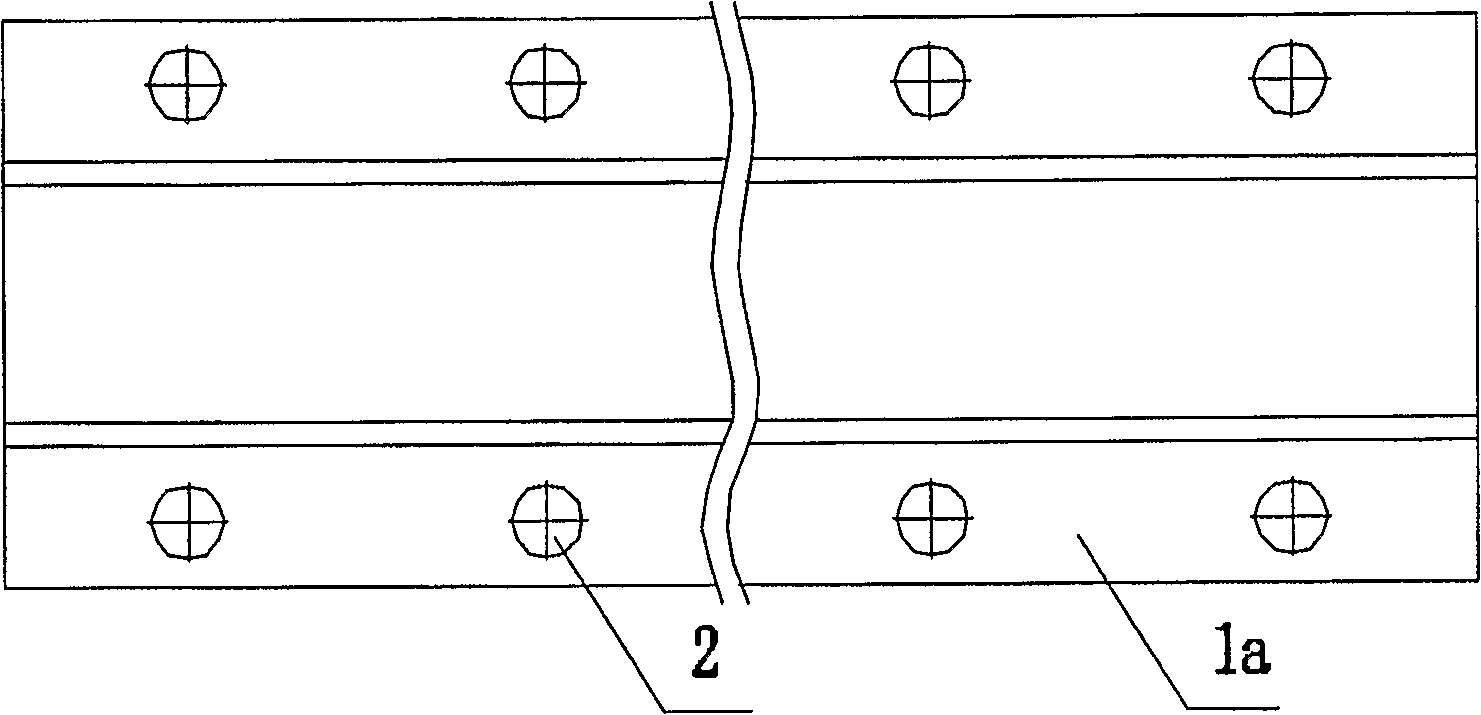
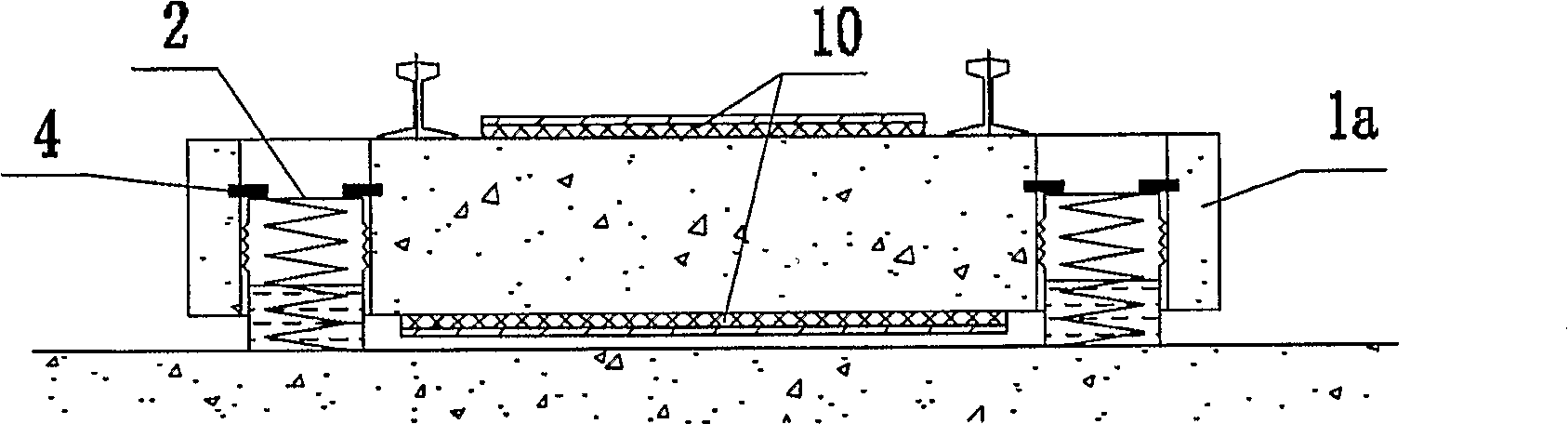
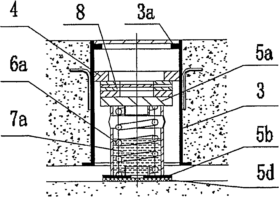
[0047] As shown in Fig. 1, Fig. 2, Fig. 3 and Fig. 4, the floating plate 1a is plate-shaped and formed by concrete pouring on site, and two rows of through holes are evenly distributed on the outer side of the floating plate corresponding to the rail; A coupling sleeve 3 is buried, and a support block 4 is welded on its inner wall. The floating plate 1a is elastically supported on the spring isolator 2 through the support block 4, forming a built-in floating ballast bed.

[0048] The internal structure of the coupling sleeve 3 and the spring isolator 2 is shown in Figure 3, including a coil spring 6a and a spring housing 5. The spring housing 5 is composed of upper and lower spring sleeves, wherein the upper sleeve is provided with a transferable The upper top plate 5a of the spring support force, the lower sleeve is provided with the lower bottom plate 5b, both are steel welded parts, sealed and connected as one by a flexible sealing ring 5c; the spring sleeve is provided with...

Embodiment 2

[0056] As shown in Figure 5, Figure 6, and Figure 7, the difference from Embodiment 1 is that the lower surface of the floating plate 1b is provided with a boss, and the spring isolator 2 is supported on the outer recess of the boss to form an external floating Set the board. The spring isolator is basically similar to that of Embodiment 1. The shape of the spring shell is a cuboid, which is composed of upper and lower sleeves and connected with rubber seals. Two coil springs 6a are placed inside, and the upper and lower ends of the coil springs are respectively embedded in solid damping material 7b. , such as high-damping viscoelastic polyurethane that can be cured after pouring, not only provides damping for the spring isolator, but also plays the role of connecting the upper and lower sleeves. Compared with liquid damping, the solid damping is not afraid of water ingress, and only from waterproof Angularly, no seal or even a spring sleeve can be provided. This multi-spring...

Embodiment 3

[0060] As shown in Fig. 8, Fig. 9, Fig. 10 and Fig. 11, compared with Example 1, the floating plate 1c is in the shape of a ladder, and the spring isolator is an external type, consisting of two parallel cast-in-place concrete beams and multiple Composed of two parallel cross-link rods 11, here is a steel pipe, the surface of the cross-link rod in the concrete beam slab is provided with anchor ribs to form a firm connection with the concrete beam slab, and constraints are provided on the upper and lower surfaces and the outer surface of the concrete beam slab The damping layer 10 is composed of a 2-3 mm thick high damping modified asphalt layer and a 2-5 mm thick steel plate bonded to each other. When the concrete beam slab is excited by the vibration of the track to generate vibration deformation, due to the inconsistent deformation of the constrained steel plate and the concrete beam slab, the damping material layer is forced to undergo shear-based deformation. Because the da...


PUM


Abstract

The present invention relates to absorption of vibration structure of the railway track bed, which comprises floating slab (1) and spring absorption of vibration apparatus (2). Thereinto, the floating slab (1) is mount on the spring absorption oaf vibration apparatus (2) elastically, so the vibration which transferring to the basement of the track bed from the rail (16) wi11 be decreased greatly by the spring absorption of vibration apparatus (2).

Description

technical field [0001] The invention belongs to a railway track bed, and in particular relates to a railway track structure, which can be specifically railways, subways, urban railways, elevated light rails, high-speed railways and the like. Background technique [0002] Traditional railway or urban railway track structure, when the distance between the line and the ground buildings is relatively close, it will have a greater impact on vibration and noise. Vibration and noise are mainly due to the unevenness and relative motion of the wheel and rail, in which the noise is transmitted to the building through the air medium (called primary noise), while the vibration is passed through the track-ballast bed-tunnel wall-foundation, or track-ballast bed -The bridge-pier-foundation is transmitted to the building, and then the low-frequency vibration of the floor is excited through the coupling amplification of the building structure itself, and the high-frequency components that h...

Claims


Application Information

Patent Timeline
Patent Type & Authority Patents(China)
IPC IPC(8): E01B19/00E01B1/00
CPCE01B19/003E01B1/002E01B19/00
Inventor 尹学军
Owner GERB QINGDAO VIBRATION CONTROL
Why Eureka
Try Eureka