Magnetic resonance receive coil with dynamic range control

A technology of receiving coils and dynamic range, applied in magnetic resonance measurement, measurement of magnetic variables, measurement devices, etc., can solve problems such as the negative influence of signal-to-noise ratio, improve signal-to-noise ratio, reduce distortion and intermodulation, and improve dynamic range. Effect

Active Publication Date: 2007-08-22
KONINKLIJKE PHILIPS ELECTRONICS NV
View PDF0 Cites 17 Cited by
  • Summary
  • Abstract
  • Description
  • Claims
  • Application Information

AI Technical Summary

Problems solved by technology

Such transmission paths can have limited dynamic range, which negatively impacts the signal-to-noise ratio

Method used


Image

  • Magnetic resonance receive coil with dynamic range control
  • Magnetic resonance receive coil with dynamic range control
  • Magnetic resonance receive coil with dynamic range control

Examples


Embodiment Construction

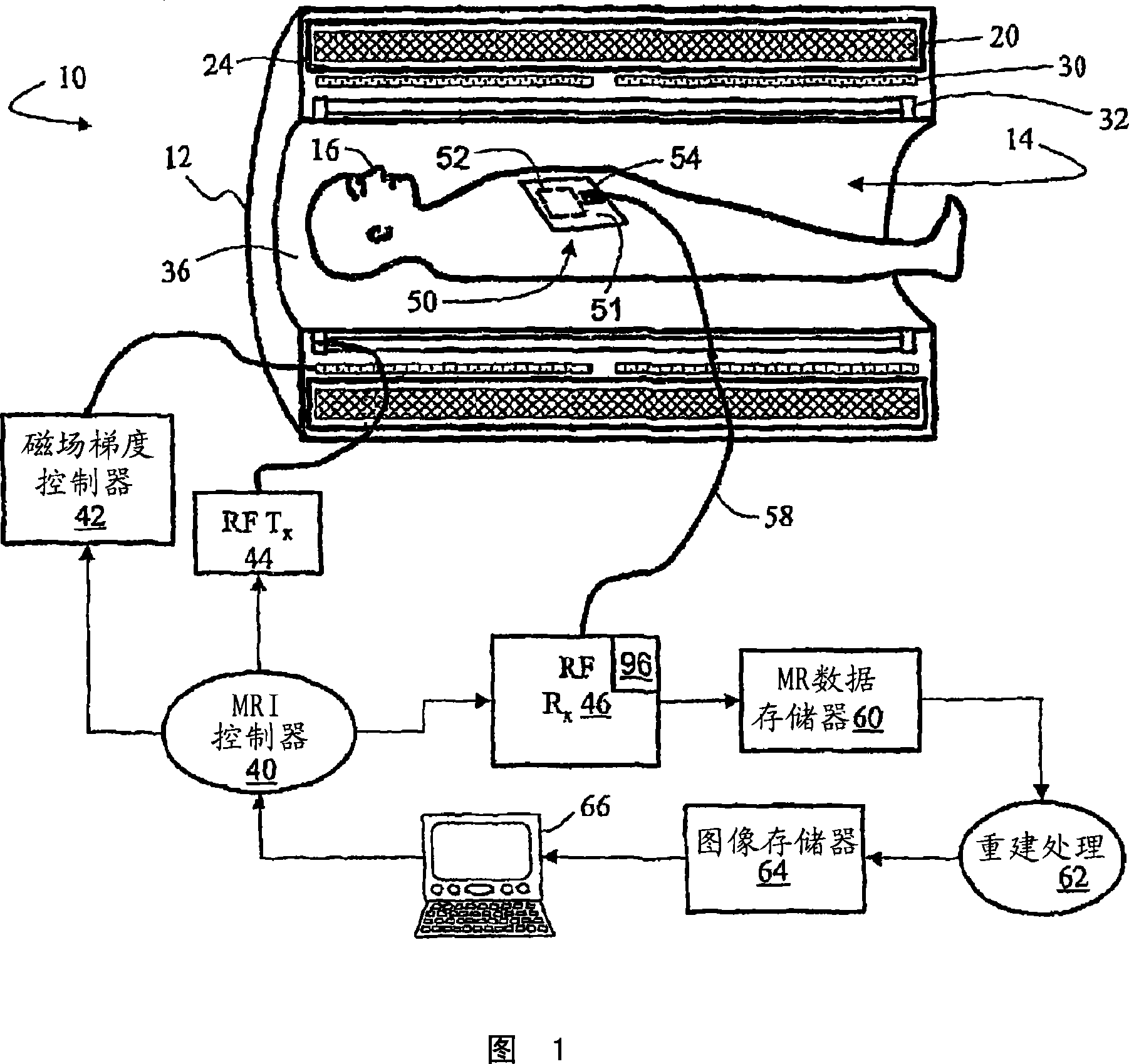
[0020] Referring to FIG. 1 , a magnetic resonance imaging scanner 10 includes a housing 12 defining a generally cylindrical scanner bore 14 within which an associated imaging subject 16 is disposed. The main magnetic field coil 20 is disposed within the housing 12 and generates a main magnetic field B directed substantially parallel to the cylindrical axis of the scanner bore 14 0 . The main field coil 20 is typically a superconducting coil disposed within a cryogenic shield 24, although a resistive main magnet could also be used. Housing 12 also houses or supports magnetic field gradient coils 30 for selectively producing magnetic field gradients in bore 14 . Housing 12 also houses or supports a radio frequency body coil 32 for selectively exciting magnetic resonance. Alternatively, magnetic resonance can be excited using head coils, surface coils, or other local coils. Housing 12 generally includes a decorative lining 36 that defines scanner aperture 14 .

[0021] The ma...


PUM


Abstract

A radio frequency receive coil (50) includes an antenna (52, 52') that is tuned to a magnetic resonance frequency to detect a magnetic resonance signal. Electronics (54) disposed on or with the antenna (52, 52') as a unitary structure include compression circuitry (102, 114, 202, 214, 230, 330, 430, 530) that compresses the magnetic resonance signal at a gain controlled by a gain control signal to produce a compressed magnetic resonance signal. The electronics (54) generate a reduced dynamic range representation of the magnetic resonance signal based on the compressed magnetic resonance signal. The reduced dynamic range representation of the magnetic resonance signal is communicated off the receive coil.

Description

technical field [0001] The invention is particularly applicable to receive coils of magnetic resonance imaging scanners and will be described with particular reference to this application. However, the present invention is applicable to general radio frequency receiving systems. Background technique [0002] For some MRI data acquisition methods, such as those in which the readout vector corresponds to a trajectory passing through the center of k-space, the dynamic range of existing analog-to-digital converters is insufficient without introducing non-negligible levels of digitization quantization noise or other detrimental In the case of noise or distortion, digitize the entire range between the noise floor and the peak signal level. [0003] For some magnetic resonance imaging scanners, the transmission path or medium between the receive coil and the analog-to-digital converter does not have sufficient dynamic range. In wireless receiving coils with limited power, it is n...

Claims


Application Information

Patent Timeline
Patent Type & Authority Applications(China)
IPC IPC(8): G01R33/36
CPCG01R33/3692G01R33/3621
Inventor K·-M·吕德克V·舒尔茨M·J·范赫尔沃尔特J·登贝夫B·L·德夫里斯
Owner KONINKLIJKE PHILIPS ELECTRONICS NV
Why Eureka
Try Eureka