Fixture

A jig and hollow technology, applied in the jig field, can solve the problems of loss of flatness, uneven distribution, workpiece deformation, etc., to avoid deformation.

Inactive Publication Date: 2007-08-29
HONG FU JIN PRECISION IND (SHENZHEN) CO LTD +1
View PDF0 Cites 19 Cited by
  • Summary
  • Abstract
  • Description
  • Claims
  • Application Information

AI Technical Summary

Problems solved by technology

When the contact surface between the workpiece 5 and the magnetic chuck 4 is a curved surface or there is bending deformation, the supporting force of the magnetic chuck to the workpiece 5 cannot be evenly distributed in the above-mentioned grinding process, which will cause deformation of the curved surface of the workpiece 5; After the force of 6 and the support force of the magnetic chuck are released, the workpiece 5 recovers its deformation, and the surface that has been processed into a plane will lose the required flatness
[0004] When the workpiece is clamped by the vise, the workpiece will be deformed after the jig is released due to the uneven distribution of the force point of the vise on the workpiece.
[0005] Therefore, as the processing precision of modern industrial products is getting higher and higher, traditional fixtures and their clamping methods will cause deformation of the workpiece and cannot meet the high-precision processing requirements.

Method used


Image

  • Fixture
  • Fixture

Examples


Embodiment Construction

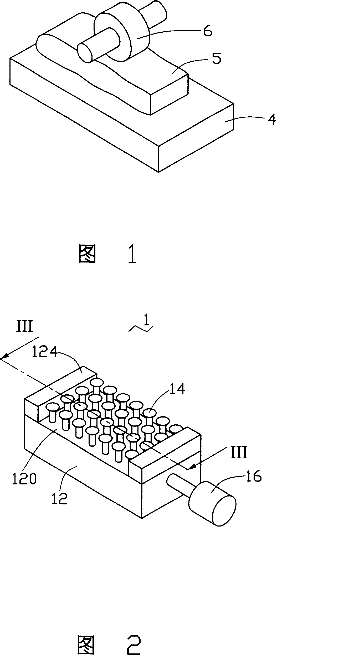
[0014] Referring to FIG. 2 , the jig 1 of the present invention includes a base plate 12 , a plurality of support rods 14 and a pressure control system 16 .

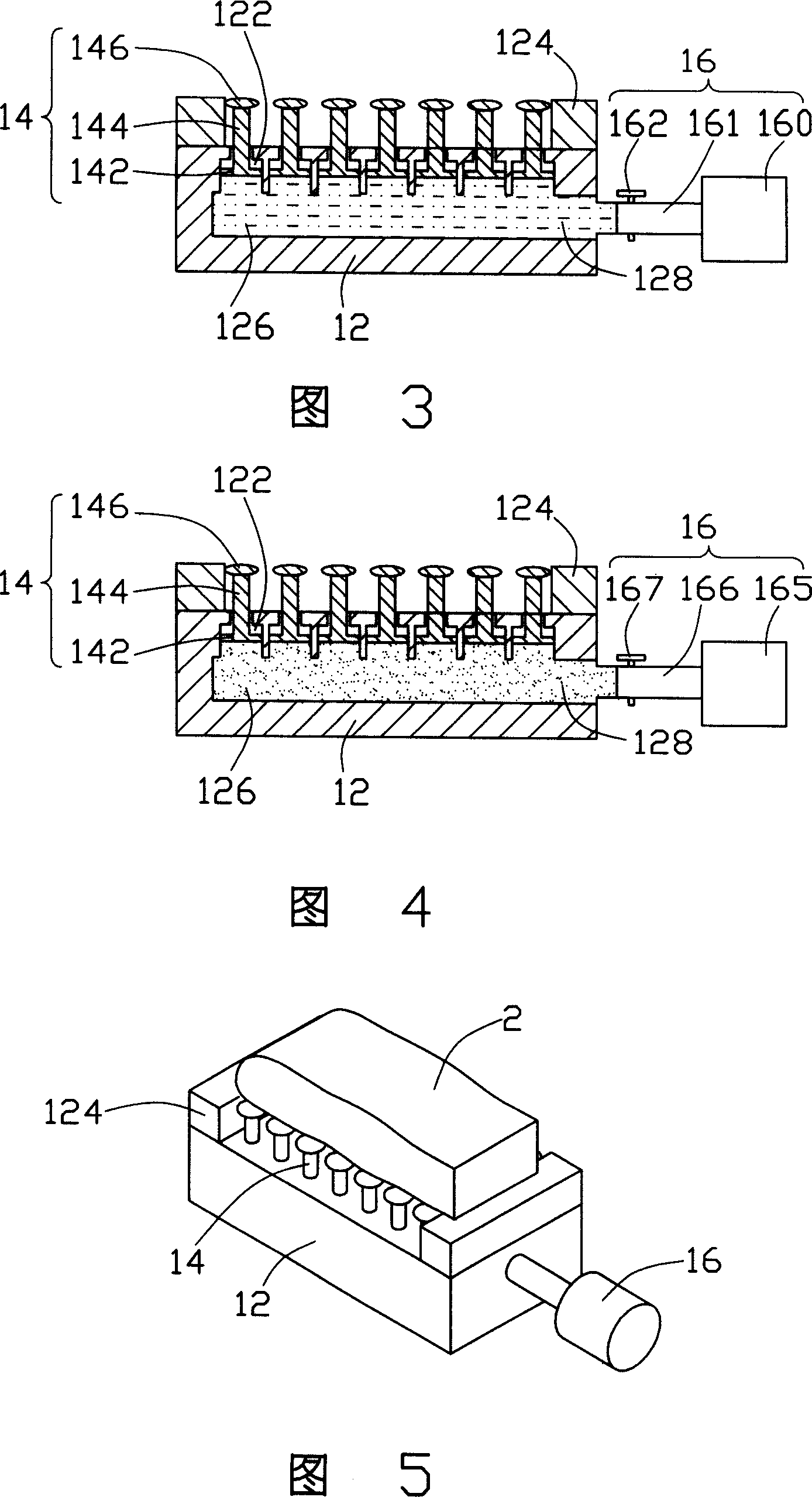
[0015] Please refer to Fig. 3 at the same time, the base plate 12 has a working surface 120 and a hollow cavity 126, two opposite edges on the working surface 120 are respectively provided with two bearing blocks 124, and the working surface 120 is provided with multiple Through holes 122 communicate with the hollow cavity 126. A channel 128 is defined on one side of the substrate 12, and the channel 128 is connected to the hollow cavity 126, so that the hollow cavity 126 can communicate with the outside world. Wherein, the hollow cavity 126 is filled with a flow medium, which can be gas or liquid.

[0016] The support rod 14 includes a piston body 142, a load bearing rod 144 and an arc contact 146. The piston body 142 is accommodated in the through hole 122 and seals the through hole 122; the load bearing rod 144 is a ...


PUM


Abstract

The invention relates to a cassette used to fix work piece. Its features are that it includes one base disk, many support bars, and one pressure control system; the base disk has one hollow cavity in which the flow medium is filled; and its one side is set many through holes connected with the hollow cavity; one end of the support bar is actively set in the through hole; another end is extended out; the pressure control system is connected with the hollow cavity and controlled the pressure of the flow medium.

Description

【Technical field】 [0001] The invention relates to a jig, in particular to a jig for clamping workpieces. 【Background technique】 [0002] The clamping fixtures used in surface grinders or processing machine tools in the prior art are generally magnetic chucks or vices, and the clamping method is direct clamping. [0003] Please refer to FIG. 1 , which is an example of using a magnetic chuck to clamp a workpiece in the grinding process. The magnetic chuck 4 holds the workpiece 5 by magnetic force, and the grinding wheel 6 grinds the surface of the workpiece 5 to process the surface of the workpiece 5 into a plane. When the contact surface between the workpiece 5 and the magnetic chuck 4 is a curved surface or there is bending deformation, the supporting force of the magnetic chuck to the workpiece 5 cannot be evenly distributed in the above-mentioned grinding process, which will cause deformation of the curved surface of the workpiece 5; After the force of 6 and the supportin...

Claims


Application Information

Patent Timeline
Patent Type & Authority Applications(China)
IPC IPC(8): B23Q3/06B25B11/00B24B41/06
CPCB23Q1/035B24B41/068
Inventor 邱文赐简扬昌
Owner HONG FU JIN PRECISION IND (SHENZHEN) CO LTD
Why Eureka
Try Eureka