Substrate integrated waveguide small-sized prism type horn antenna

A substrate-integrated waveguide and horn antenna technology, applied to waveguide horns, antennas, electrical components, etc., can solve problems such as designing horn antennas, and achieve the effects of low return loss, high gain, and easy camouflage

Inactive Publication Date: 2007-08-29
NANJING UNIV OF SCI & TECH
View PDF0 Cites 48 Cited by
  • Summary
  • Abstract
  • Description
  • Claims
  • Application Information

AI Technical Summary

Problems solved by technology

However, no one has used this new pla

Method used


Image

  • Substrate integrated waveguide small-sized prism type horn antenna

Examples


Example Embodiment

[0012] The present invention will be further described in detail below in conjunction with the accompanying drawings.

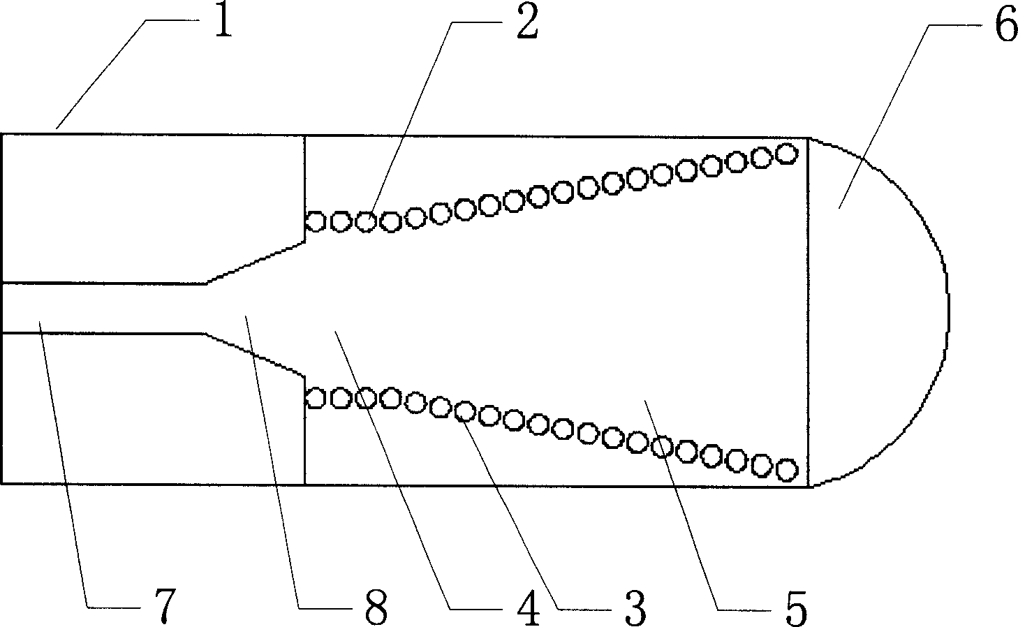
[0013] With reference to the drawings, the substrate integrated waveguide prism horn antenna of the present invention includes a dielectric substrate 1, the thickness of the dielectric substrate 1 is 2mm, the thickness of the dielectric substrate 1 can be 0.32λ~0.49λ, and the dielectric constant is 10.2. The dielectric constant of the dielectric substrate 1 may range from 2-15. Two rows of metal pillars 2, 3 are arranged on the dielectric substrate 1, and the two rows of metal pillars 2, 3 respectively form the interconnected substrate integrated rectangular waveguide 4 and the H-face horn section 5. The two rows of metal pillars 2, 3 form H Face the two walls of the horn section with 5 openings, the radius of the metal pillars of the two rows of metal pillars 2, 3 is 0.4mm, and the distance between the two adjacent metal pillars is 1mm. The diameter of the metal...


PUM


Abstract

This invention relates to a substrate integrated waveguide prism-like horn antenna including a medium base board, in which, two rows of metal posts are set on the medium base board and form a substrate integrated rectangular waveguide and a H-side horn section connected mutually, an arc radiation side connected with the medium base board is set on two walls of the opening of the H-side horn section and the horn mouth, the two rows of metal posts are connected with micro-band feed lines composed of a line of 50Ohm and a transformation taper, and the waveguide and the up and down surfaces of the medium base board are metals.

Description

a technical field [0001] The invention relates to a miniaturized horn antenna, in particular to a substrate-integrated waveguide miniature prism horn antenna. Two background technology [0002] As an important member of the antenna family, the horn antenna plays a role in the smooth transition from the waveguide mode to the free space mode. This smooth transition reduces reflections and thus enhances radiation. The horn antenna has the characteristics of high gain, small reflection and wide operating frequency band, and it is easy to realize in technology. The commonly used horn antenna is composed of a waveguide section and a horn with a certain opening angle and length. It has good directivity and high gain, but it is bulky and difficult to integrate with planar circuits, so it is difficult to meet the development of modern technology. Requirements for miniaturization and integration of devices and systems; microstrip lines have the advantages of small size, light weight...

Claims


Application Information

Patent Timeline
IPC IPC(8): H01Q13/00H01Q13/02H01Q13/08
Inventor 车文荃符兵周雍徐磊王大朋邓宽
Owner NANJING UNIV OF SCI & TECH
Why Eureka
Try Eureka