
Motor drive device

一种驱动装置、电动机的技术,应用在起动的装置、电子换向电动机控制、单个电动机转速/转矩控制等方向,能够解决不能检测转子位置的区域、逆转或同步骤偏离、难以适用等问题,达到品质良好、缩短期间、容易实现的效果

Inactive Publication Date: 2007-08-29
PANASONIC CORP
View PDF4 Cites 19 Cited by
  • Summary
  • Abstract
  • Description
  • Claims
  • Application Information

AI Technical Summary

Problems solved by technology

Therefore, it is difficult to apply when obtaining autonomous controllability or an inexpensive motor drive system from the motor.
[0016] In Patent Document 3, there is a problem that there is an area where the rotor position cannot be detected
In this area, the motor stops when starting, no matter how the rotor search pulse is applied, the motor may be in a stopped state, resulting in the problem of not being able to start
In addition, when the rotor position cannot be detected correctly like this, even if the initial position search process of the rotor position is switched to the reverse induced voltage mode, there is a problem of reverse or step deviation.

Method used


Image

  • Motor drive device
  • Motor drive device
  • Motor drive device

Examples


no. 1 approach

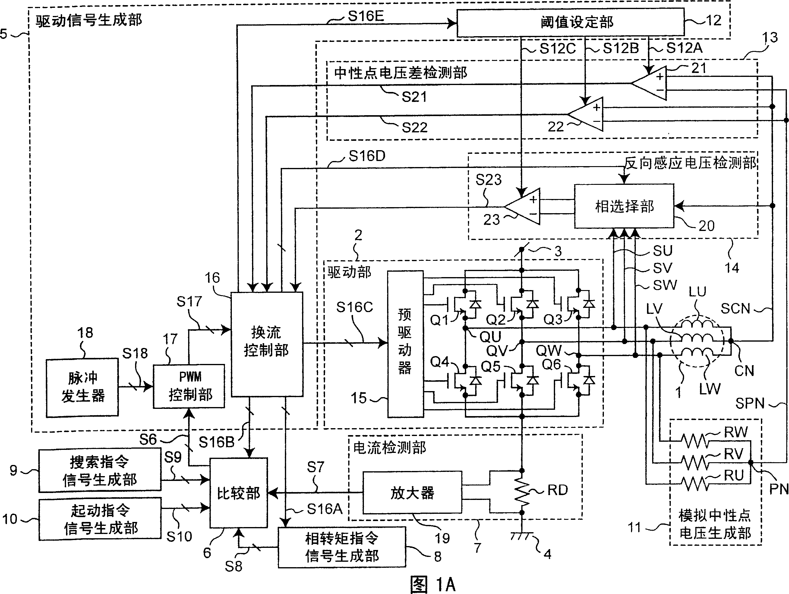
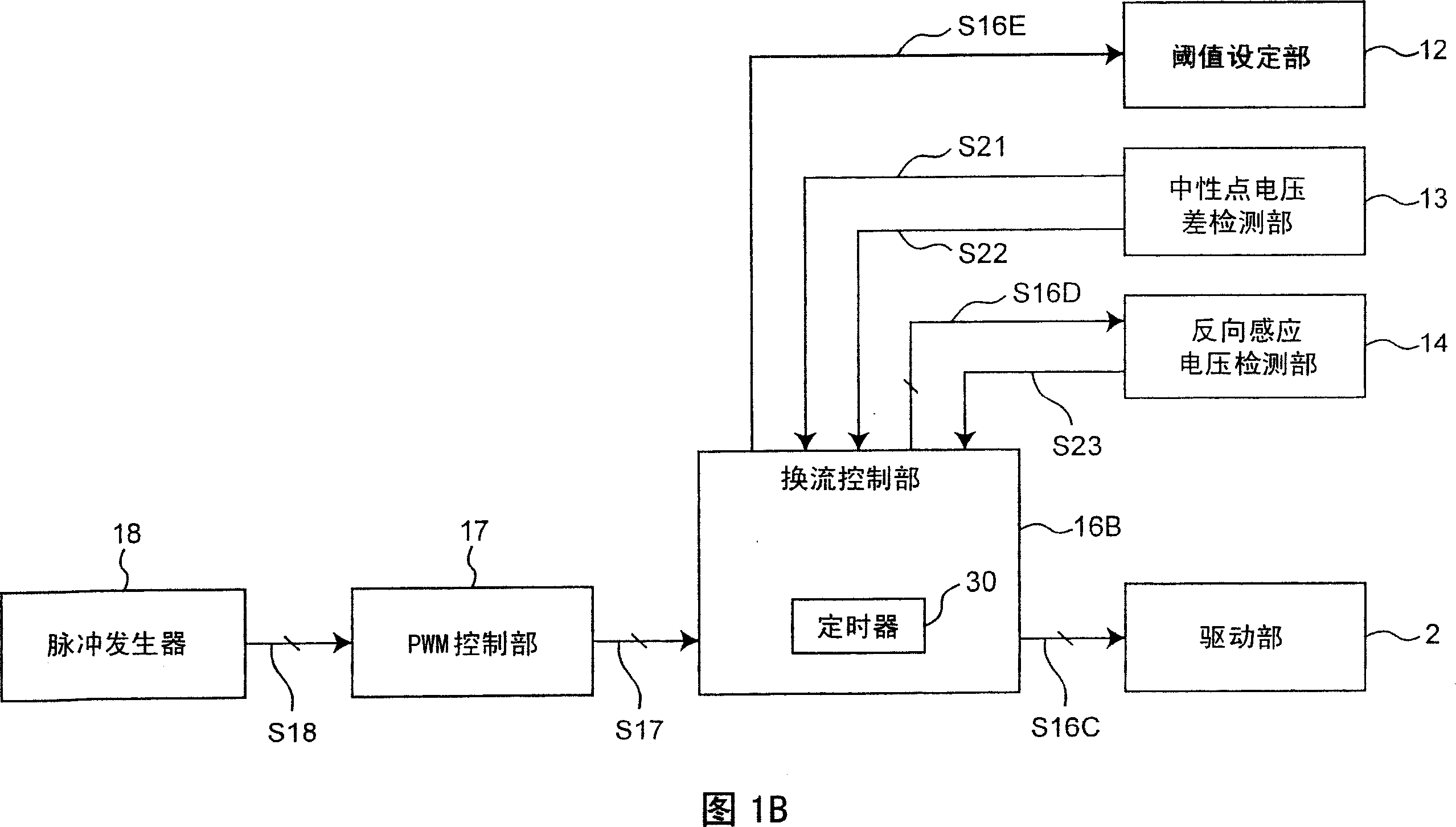
[0066] FIG. 1A shows a circuit configuration in a first embodiment of a motor drive device according to the present invention. In FIG. 1A , the motor drive device includes a motor 1, a drive unit 2, a drive signal generation unit 5, a comparison unit 6, a current detection unit 7, a phase torque command signal generation unit 8, a search command signal generation unit 9, a start command signal A generation unit 10 , an analog neutral point voltage generation unit 11 , a neutral point voltage difference detection unit 13 , and a reverse induced voltage detection unit 14 .

[0067] The motor 1 includes a three-phase stationary stator and a rotor rotating around the stator. In the first embodiment, the three-phase motor 1 is used as the motor, but the present invention can be applied to an N-phase motor by setting N to an integer greater than or equal to 2. The U-phase motor coil LU, V-phase motor coil LV, and W-phase motor coil LW wound in the stator are connected in common thr...

no. 2 approach

[0403] In the first embodiment, the case of two-phase energization has been described. In the second embodiment, the case of three-phase energization will be described focusing on points different from the first embodiment described above. Other configurations, actions, and effects are the same as those of the first embodiment.

[0404] FIG. 20 shows a circuit configuration of a second embodiment of the motor drive device according to the present invention. In FIG. 20 , the motor drive device includes a motor 1, a drive unit 2, a drive signal generation unit 5, a comparison unit 6, a current detection unit 7, a phase torque command signal generation unit 8, a search command signal generation unit 9, a start command signal Generating unit 10 , analog neutral point voltage generating unit 11 , neutral point voltage difference detecting unit 13A, and reverse induced voltage detecting unit 14A.

[0405] The motor 1 includes a three-phase fixed stator and a rotor rotating around ...


PUM


Abstract

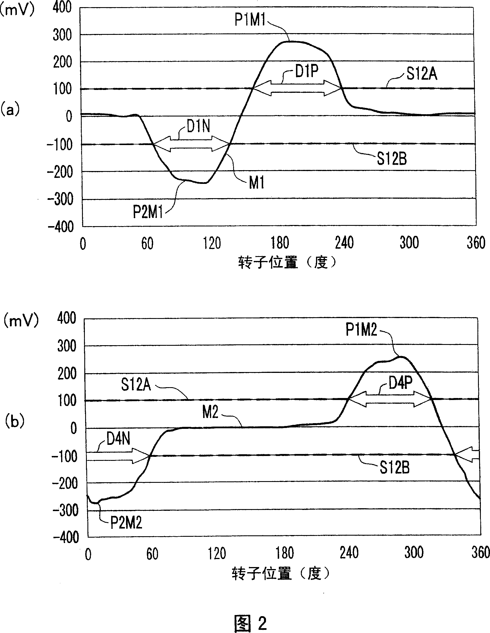
Problems with accuracy reading position detection signal peaks and minute phase differences in the detection current make motor drive control easily susceptible to differences in motor characteristics. The rotor position is determined based on whether or not a neutral point difference voltage, which is the difference voltage between the neutral point voltage and the pseudo-neutral-point voltage when the motor phases are selectively energized, exceeds a specific threshold value. The phase energized to start the motor is determined based on this determination and the motor is energized accordingly to start. Instead of switching directly from the search step at the initial rotor position to the back-EMF voltage mode, a search and start mode that creates initial rotor speed sufficient to start the motor is executed before entering the back-EMF voltage mode.

Description

technical field [0001] The present invention relates to a three-phase brushless motor drive technology capable of stably and rapidly starting without a rotor position sensor. Background technique [0002] In the brushless motor, the stator selects an appropriate coil, and flows a current to provide a stable torque to the rotor. Therefore, the electrical relative position of the rotor to the stator is required. In order to know this relative position, various rotor position sensors are used. On the other hand, in terms of reliability, cost increase, and environmental resistance, sensorless drive technology that does not require a rotor position sensor has also been developed. Among such sensorless driving techniques, there is generally known a technique of detecting a rotor position by reading a reverse induced voltage generated in a stator phase coil when the rotor rotates. However, since the reverse induced voltage is not generated when the rotor is stopped, various dete...

Claims


Application Information

Patent Timeline
Patent Type & Authority Applications(China)
IPC IPC(8): H02P6/18H02P6/06H02P6/08H02P6/182H02P6/21
CPCH02P6/182H02P6/205H02P6/21
Inventor 深水新吾山本泰永黑岛伸一
Owner PANASONIC CORP
Learn More