Automatic skip blanking apparatus of thread rolling machine

An automatic loading and unloading and thread rolling machine technology, applied in the direction of feeding device, thread cutting device, tangential feeding device, etc., can solve the problems of low productivity of manual loading and unloading, industrial accidents, etc., to increase labor productivity, reduce waste, reduce The effect of industrial accidents

Inactive Publication Date: 2007-09-05
陈显国
View PDF0 Cites 9 Cited by
  • Summary
  • Abstract
  • Description
  • Claims
  • Application Information

AI Technical Summary

Problems solved by technology

The productivity of manual loading and unloading is very low, and accidents may occur if the operator is not careful

Method used


Image

  • Automatic skip blanking apparatus of thread rolling machine
  • Automatic skip blanking apparatus of thread rolling machine
  • Automatic skip blanking apparatus of thread rolling machine

Examples


Embodiment 1

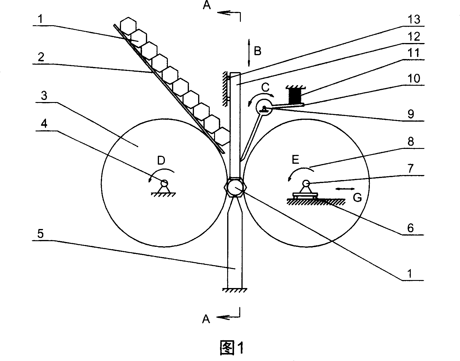
[0015] Fig. 1 is the structural representation of the present invention when feeding, including: 1. workpiece (screw blank, or the screw of making), 2. feeding chute, 3. fixed thread rolling wheel, 4. fixed thread rolling wheel center of rotation , 5. The workpiece support plate, 6. Moving the sliding guide rail of the rolling wheel, 7. The center of rotation of the moving rolling wheel, 8. The moving center of the rolling wheel, 9. The center of rotation of the feeding baffle, 10. The feeding baffle, 11 . Feeding baffle spring, 12. Feeding push rod, 13. Feeding push rod sliding guide.

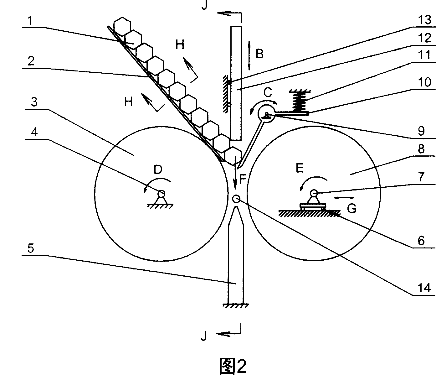
[0016] Fig. 2 is the structural representation of the present invention when discharging, in the figure: 14. discharging push rod.

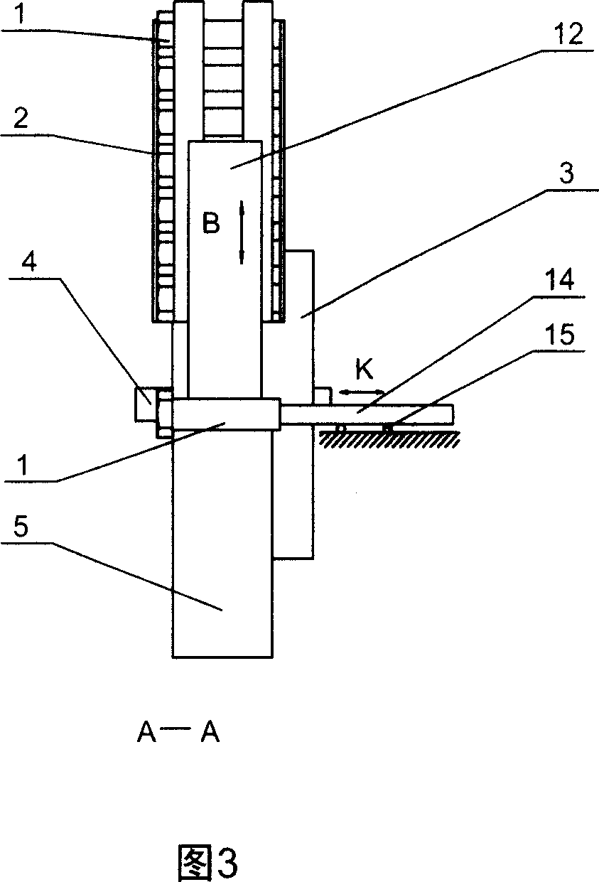
[0017] Fig. 3 is a schematic diagram of the structure of the present invention in the direction of A-A during material feeding, in the figure: 15. The sliding guide rail of the discharging push rod. Fig. 4 is a schematic diagram of the J-J direction structure of...

Embodiment 2

[0027] In this embodiment, other parts are the same as in Embodiment 1, and the difference is the pushing mechanism of the material-feeding and material-feeding push rods. The material-feeding and material-feeding push rod pushing mechanisms used in this embodiment are hydraulic cylinders. A hydraulic cylinder is connected to the feed push rod, and a hydraulic cylinder is also connected to the discharge push rod. The up and down, front and rear reversing of the two hydraulic cylinders are provided by the reversing valve, and the reversing signal comes from the position of the moving roller box. sensor.


PUM


Abstract

An automatic feeding-discharging mechanism for a screw rolling machine is composed of a feeding chute with an inclined angle (0-90 deg.), a vertical feeding push rod and its driver, a feeding barrier with a spring, a horizontal discharging push rod, and the driver for horizontal discharging push rod.

Description

technical field [0001] The invention relates to an automatic loading and unloading device of a thread rolling machine, in particular to an automatic loading and unloading device on a fast thread rolling machine used in the process of producing screws, and is a mechanical device. Background technique [0002] Known thread rolling machines for producing screws usually use manual loading and unloading. At the beginning of processing, the operator puts the screw blank without thread between the two thread rolling wheels, and after the thread rolling, the operator takes the screw out from the middle of the two thread rolling wheels. Screw production is a kind of super-mass production, which requires that the operation time of each process must be very short in order to meet the requirements of high productivity. The productivity of manual loading and unloading is very low, and accidents may be caused if the operator is not careful. Contents of the invention [0003] The purpo...

Claims


Application Information

Patent Timeline
Patent Type & Authority Applications(China)
IPC IPC(8): B21H9/02B23G11/00
Inventor 陈显国
Owner 陈显国
Why Eureka
Try Eureka