Ceramic hot-blast furnace by emusified coking slurry cyclone burner

A technology of cyclone combustion and hot blast stove, which is applied in the direction of burning with various fuels, combustion chambers, and burning with block fuels and liquid fuels, and can solve the problems of failure to reach the melting point of emulsified coke slurry ash and slag, energy waste, and manufacturing High cost and other issues, to achieve continuous and effective liquid slag removal, efficient and stable combustion, and improved cleanliness

Inactive Publication Date: 2007-09-05
GUANGZHOU DEVOTION THERMAL TECH
View PDF4 Cites 5 Cited by
  • Summary
  • Abstract
  • Description
  • Claims
  • Application Information

AI Technical Summary

Problems solved by technology

It can be seen from the above analysis that, firstly, the backfired coal-water slurry liquid slagging combustion furnace is not suitable for the combustion of emulsified coke slurry; secondly, the combustion chamber temperature of the backfired coal water slurry liquid slagging combustion furnace is still low The ash melting point of the emulsified coke slurry ash cannot be reached, and the emulsified coke slurry ash cannot be liquefied; finally, the combustion chamber str...

Method used


Image

  • Ceramic hot-blast furnace by emusified coking slurry cyclone burner
  • Ceramic hot-blast furnace by emusified coking slurry cyclone burner
  • Ceramic hot-blast furnace by emusified coking slurry cyclone burner

Examples


Embodiment 1

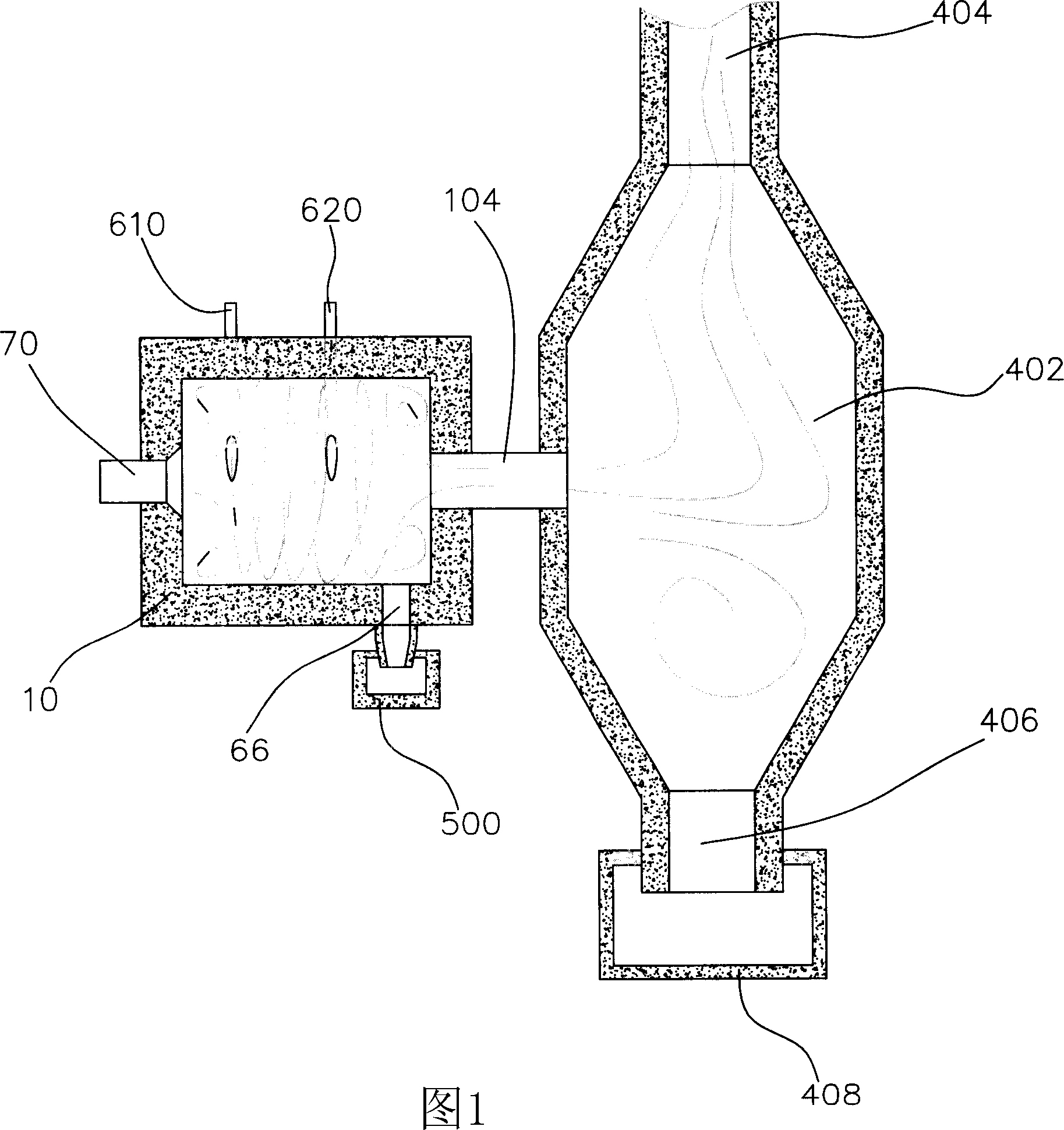
[0051] Please refer to Fig. 1, the ceramic hot blast stove adopting the emulsified coke slurry cyclone combustion device of the present invention includes a vertical hot blast stove body and an emulsified coke slurry cyclone combustion device. Wherein, the hot blast stove body includes an oval furnace chamber 402, a hot blast outlet 404 positioned at the top of the oval furnace chamber 402, a secondary slag outlet 406 positioned at the bottom of the oval furnace chamber 402, and two outlets below the secondary slag outlet 406. Secondary slagging device 408. The emulsified coke slurry cyclone combustion device includes a shell 10 , an emulsified coke slurry burner 70 , an oil burner (not shown in the figure), a gas burner (not shown in the figure), and a primary slagging device 500 . The emulsified coke slurry cyclone combustion device communicates with the middle part of the oval furnace cavity 402 through the pipeline 104 .

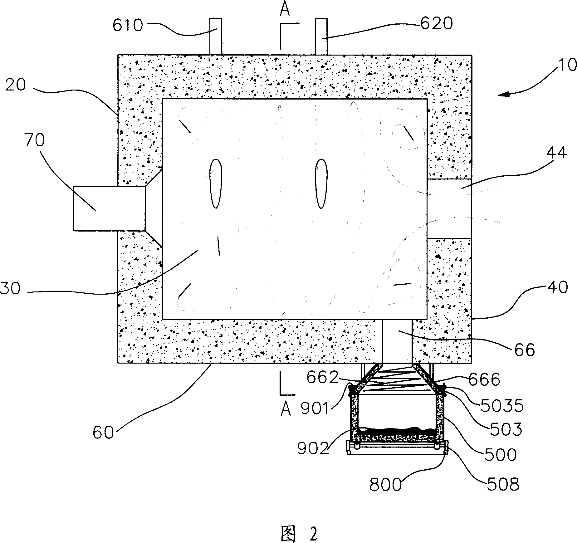
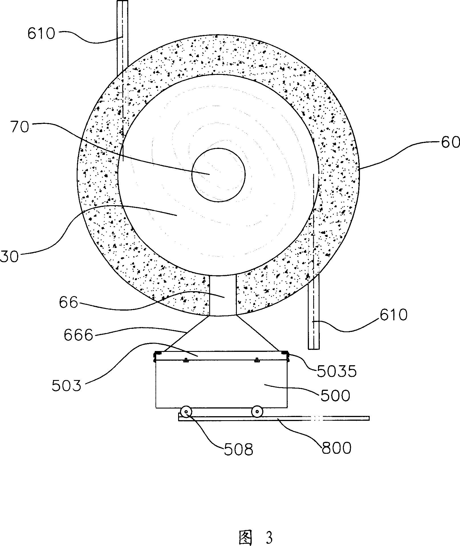
[0052] Figure 2 and Figure 3 specifically disclos...

Embodiment 2

[0072] Please refer to Figure 4 and Figure 5, this embodiment is similar to Embodiment 1, the difference is:

[0073] Since the amount of slag discharged from the secondary slag outlet 406 is small, instead of alternately working slag discharge vehicles, a slag discharge container is used, and the slag discharge container is emptied or replaced at regular intervals.

[0074] The opening area of ​​the liquid slag outlet 66 on the inner wall of the side wall 60 is approximately equal to one-twentieth of the cross-sectional area of ​​the combustion space 30 .

[0075] The vertical distance between the inner wall of the front end wall 20 and the inner wall of the rear end wall 40 is 1.5 times the inner diameter of the combustion space 30 .

[0076] The diameter of the outlet 44 is about half of the inner diameter of the combustion space 30 , and a conical transition chamber 48 is formed between the outlet 44 and the side wall 60 of the housing 10 . That is, a flared opening is fo...

Embodiment 3

[0085] This embodiment is similar to Embodiment 1, the difference is:

[0086] The ceramic hot blast stove using the emulsified coke slurry cyclone combustion device is provided with two liquid slag outlets 66 of the same size distributed at intervals, and the opening area of ​​each liquid slag outlet 66 on the inner wall of the side wall 60 is approximately equal to the cross-sectional area of ​​the combustion space one-thirtieth of.

[0087] The two liquid slag outlets 66 are surrounded by the same transition cavity 666 and are connected to the slag holding space 505 of the same slag discharge vehicle 500 .

[0088] The vertical distance between the inner wall of the rear end wall 40 and the inner wall of the front end wall 20 is 4 times the inner diameter of the combustion space 30 .

[0089] The wind speed of the tangential wind delivered to the combustion space 30 by each tangential wind inlet is 28 m / s. Three groups of tangential air inlets with a total flow rate of 0....


PUM


Abstract

This invention discloses a ceramic air heating furnace with the emulsification slurry wind burning device including vertical air heating furnace and the emulsification slurry wind burning device. The air heating furnace includes an egg-shape furnace chamber and the heat air opening. The emulsification burning device consists of a front end wall, back end wall and the side crust inside which forms a cylindraceous burning space. There are at least one emulsification burning device and at least a fuel burning device or at least air burning device. The back end wall has an outlet opening which connects to the egg-shape furnace chamber by the pipe. The side of the crust sets two or more tangential wind inlet openings and there are at least one dreg outlet opening near the back end wall at the side of the bottom of the burning space. The ceramic air heating furnace of this invention utilizes the emulsification burning device and the emulsification slurry as fuel so as to save the cost and maximize the utilization of the resource.

Description

technical field [0001] The invention relates to a ceramic hot blast stove, in particular to a ceramic hot blast stove using an emulsified coke slurry burning device. Background technique [0002] Generally, the relatively clean energy used by ceramic hot blast stoves is mainly oil, natural gas or coal gas. However, this has greatly increased the fuel cost of ceramic hot blast stoves, seriously affecting the survival of companies that use and manufacture ceramic hot blast stoves. [0003] For this reason, those skilled in the art are working hard to develop new available energy sources. Inexpensive, efficient and clean emulsified coke slurry fuel has gradually become a new favorite in this field. The use of emulsified coke slurry fuel in ceramic hot blast stoves can not only make reasonable use of natural resources, but also reduce the fuel cost of ceramic hot blast stoves. Therefore, countries all over the world are vigorously promoting emulsified coke slurry combustion tec...

Claims


Application Information

Patent Timeline
IPC IPC(8): F23C1/00F23C3/00F23C5/00F23C7/00F23J1/08F24H3/04
CPCY02B30/28Y02B30/00
Inventor 常厚春李祖芹马革刘效洲
Owner GUANGZHOU DEVOTION THERMAL TECH
Why Eureka
Try Eureka