Controlling circuit and loading system therewith

A technology for controlling circuits and load systems, applied in electrical components, pulse amplitude modulation, pulse frequency/rate modulation, etc., can solve the problems of poor transient response, low sensitivity, and prolonged time for the system to reach a steady state, and achieve high stability. degree of effect

Inactive Publication Date: 2007-09-05
BEYOND INNOVATION TECH
View PDF0 Cites 17 Cited by
  • Summary
  • Abstract
  • Description
  • Claims
  • Application Information

AI Technical Summary

Problems solved by technology

[0007] (1) In the conventional pulse width modulation control circuit, since the width of the pulse control signal is modulated by the error between the feedback voltage and the reference voltage, the noise of the feedback voltage will directly affect the pulse control signal. Width makes a difference
[0008] (2) The load system with the conventional pulse width modulation control circuit with high sensitivity will have a better transient response due to the setting of the time constant, but it will cause excessive transients and greatly reduce the stability of the system stability
[0009] (3) The load system with conventional pulse width modulation control circuit with low sensitivity will have a poor transient response due to the setting of the time constant, but the time for the system to reach a steady state will be prolonged, which will increase the stability of the system. state stability

Method used


Image

  • Controlling circuit and loading system therewith
  • Controlling circuit and loading system therewith
  • Controlling circuit and loading system therewith

Examples


Embodiment Construction

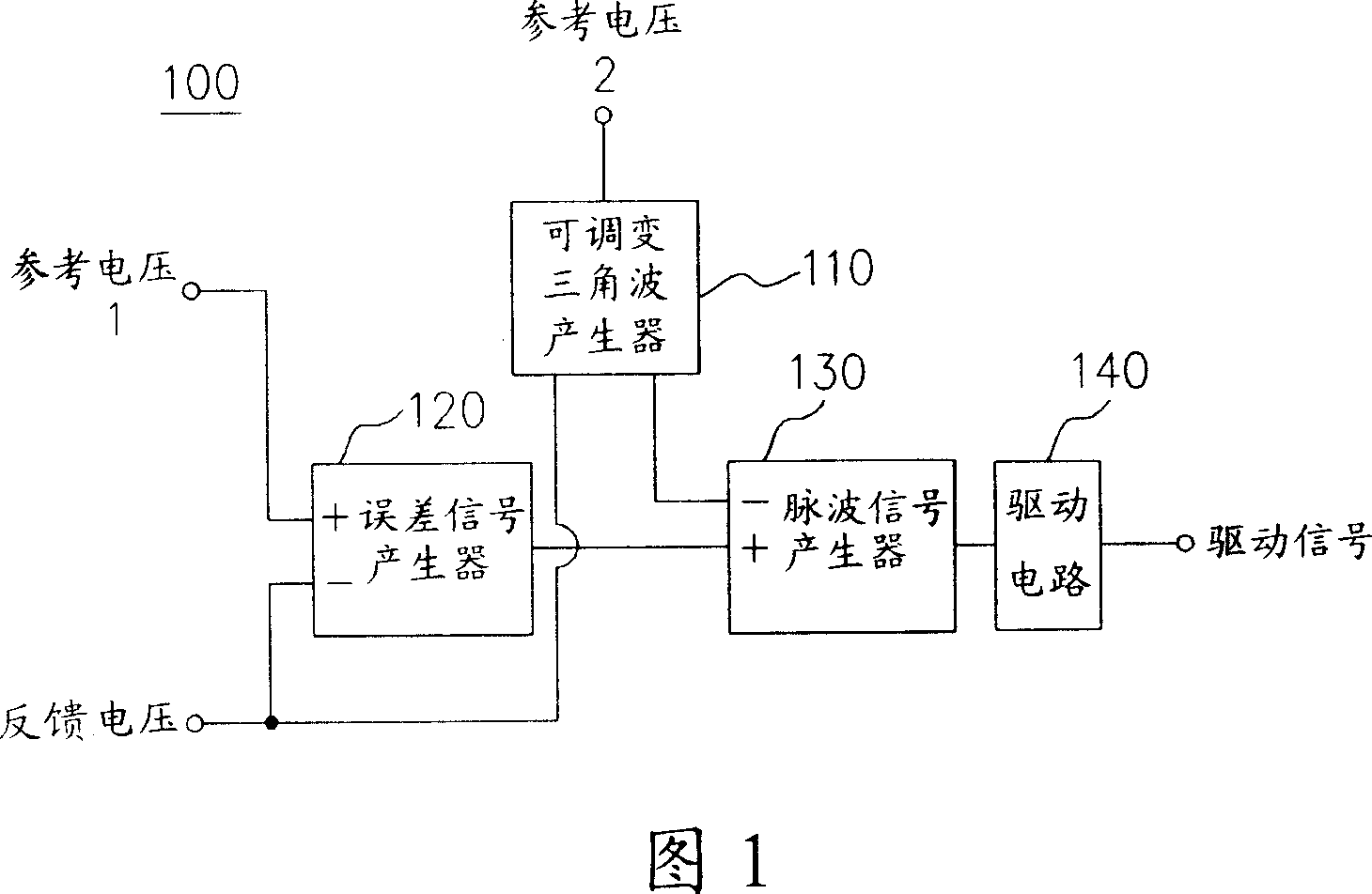
[0046] Please refer to FIG. 1 , which shows a circuit block diagram of a PWM control circuit according to a preferred embodiment of the present invention. In FIG. 1 , the pulse width modulation control circuit 100 includes an adjustable triangular wave generator 110 and a driving signal generating circuit. The driving signal generating circuit includes an error signal generator 120, a pulse signal generator 130 and a driving circuit 140. . The adjustable triangular wave generator 110 receives the reference voltage 2 and the feedback voltage indicating the state of the load circuit for calculation to determine the frequency and amplitude of the output triangle wave. The error signal generator 120 performs calculations for the reference voltage 1 and the feedback voltage to output an error signal. The pulse signal generator 130 is respectively coupled to the adjustable triangular wave generator 110 and the error signal generator 120 to compare the error signal with the adjustable ...


PUM


Abstract

The invention is concerned with the controlling circuit and loading system that uses the controlling circuit, the controlling circuit consists of the adjustable triangle wave generator, the error signal generator, and the pulse wave signal generator. The adjustable triangle wave generator uses the reference voltage and the feedback voltage to be the amplitude modulation and the frequency operation, outputs different amplitude and frequency triangle wave by the continuity or section mode, the error signal generator does the error operation for the reference voltage and the feedback voltage and outputs the error signal, the pulse signal generator outputs the pulse wave signal that the controlling voltage source supplies the loading system voltage according to the error signal and the adjustable triangle wave.

Description

technical field [0001] The present invention relates to a pulse width modulation control circuit, and in particular to an adjustable amplitude and frequency triangular wave generator, which outputs a triangular wave whose amplitude and frequency change with the working state according to the current working state of the load system , to control the pulse width modulation control circuit to change the width and frequency of the pulse control signal output by it, so as to improve the transient response of the load system. Background technique [0002] Pulse Width Modulation (Pulse Width Modulation, PWM for short) is a traditional and practical control method, which is widely used in many control systems with feedback circuits, such as boost circuit, step-down circuit, push-pull circuit, half-bridge circuit and full-bridge circuit. In these circuits, the obtained feedback voltage is processed by the error amplifier (Error Amplifier), and the triangle wave (Triangle Wave) with ...

Claims


Application Information

Patent Timeline
Patent Type & Authority Applications(China)
IPC IPC(8): H03K4/06H03K7/02H03K7/06H02M1/08
Inventor 李立民余仲哲
Owner BEYOND INNOVATION TECH
Why Eureka
Try Eureka