Airplane intake lip

A technology of air inlet and lip, which is applied in the field of aircraft structure design, can solve the problems of reducing lip life, affecting lip strength, expensive dies, etc., and achieves the effects of prolonging service life, improving structural strength, and high dimensional accuracy

Inactive Publication Date: 2007-09-12
JIANGXI HONGDU AVIATION IND GRP
View PDF0 Cites 10 Cited by
  • Summary
  • Abstract
  • Description
  • Claims
  • Application Information

AI Technical Summary

Problems solved by technology

The local thickness of the front end of the lip of sheet metal stamping parts is extremely thin, which affects the strength of the lip, and requires expensive dies, which increases the manufacturing cost; the welding process affects the strength, precision and aerodynamic shape of the part, reducing the life of the lip
In addition, the lip welded after sheet metal stamping cannot withstand large loads
Casting parts are large in size, heavy in weight, poor in surface quality, low in strength and manufacturing precision; in addition, casting molds will also increase manufacturing costs

Method used


Image

  • Airplane intake lip
  • Airplane intake lip

Examples


Embodiment Construction

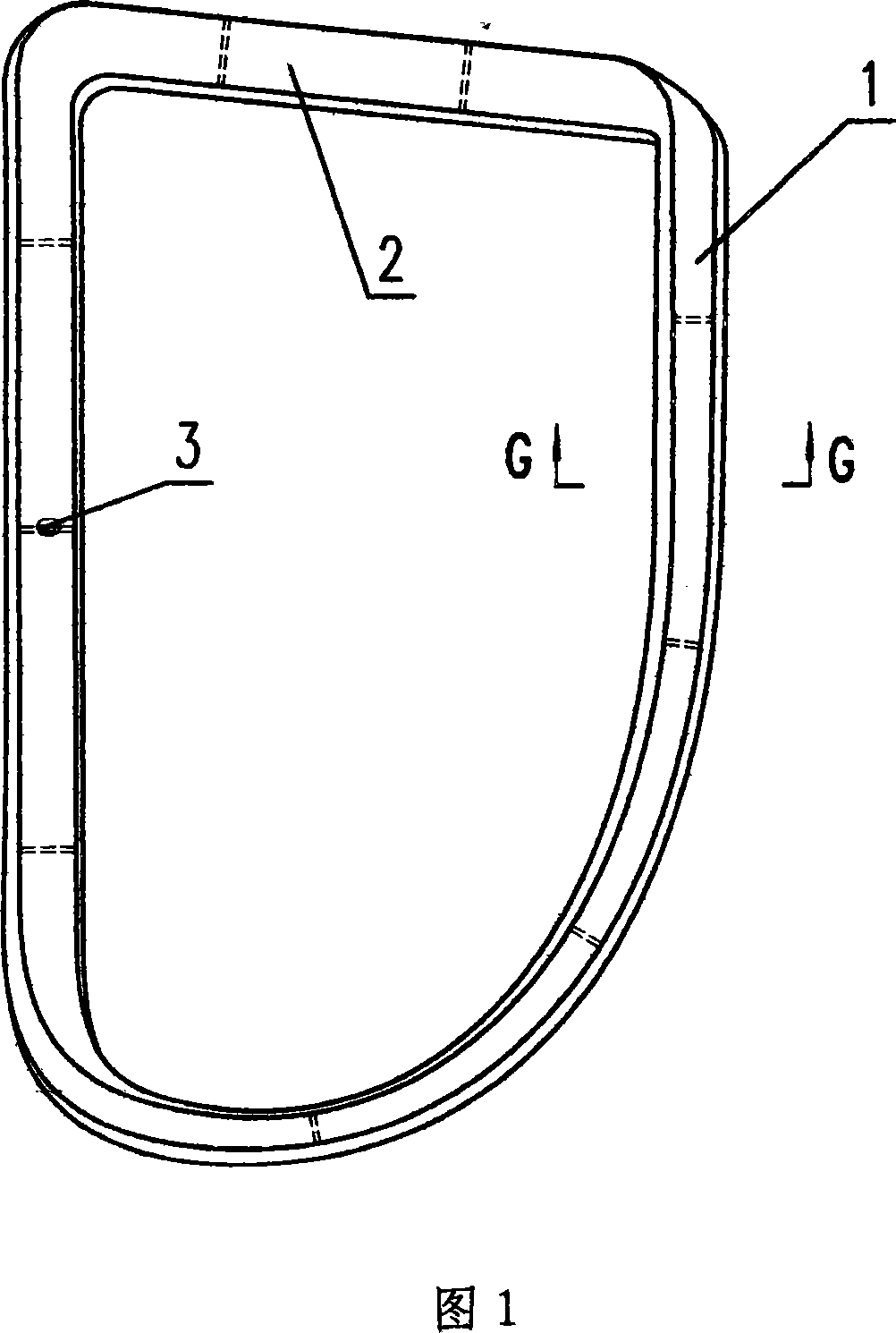
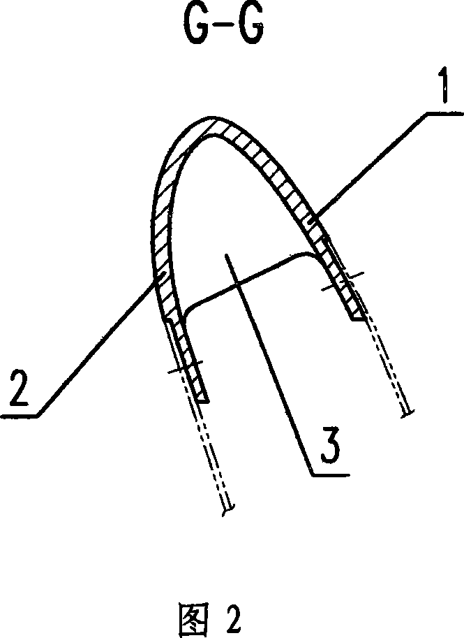
[0009] The present invention will be described in further detail below. Referring to Fig. 1, the aircraft inlet lip of the present invention is a ring formed by connecting the annular lip outer wall 1 and the inner wall 2, and its cross-sectional shape is a thin-walled U-shape, and the outer lip inner wall 2 The edge of the surface has a joint surface that matches the front end of the skin of the air inlet. The shape of the outer lip wall 1 matches the shape of the skin of the fuselage where the air inlet is located. A skin-fit joint surface, characterized in that,

[0010] (1) Between the outer wall 1 and the inner wall 2 of the lip, there are reinforcing ribs 3 distributed along the circumferential direction, and the distance L between two adjacent reinforcing ribs 3 along the circumferential direction is 200-400mm;

[0011] (2) The lip is formed by machining a plate as a whole.

[0012] In one embodiment of the present invention, there are nine ribs 3 along the circumfere...


PUM


Abstract

The present invention relates to airplane structure design, and is especially improved lip for intake duct of airplane. The improved lip for intake duct is one ring part comprising connected ring lip outer wall and ring lip inner wall, features that between the ring lip outer wall and the ring lip inner wall, there are reinforcing ribs distributed in the circumference direction and in the interval of 200-400 mm and that the lip is formed integrally with plate material through a machining process. The improved lip has high dimensional precision, good pneumatic appearance, greatly raised strength, great load bearing capacity and long service life.

Description

technical field [0001] The invention belongs to the field of aircraft structure design and relates to the improvement of the air intake lip of the aircraft. Background technique [0002] The shape of the air intake lip of an aircraft is a complex curved surface, and now it is generally manufactured by segmented sheet metal stamping followed by welding or casting. The local thickness of the front end of the lip of sheet metal stamping parts is extremely thin, which affects the strength of the lip, and requires expensive dies, which increases the manufacturing cost; the welding process affects the strength, precision and aerodynamic shape of the part, reducing the life of the lip. In addition, the lip welded after sheet metal stamping cannot withstand large loads. Casting parts have large size, heavy weight, poor surface quality, low strength and low manufacturing precision; in addition, casting molds will also increase manufacturing costs. Contents of the invention [000...

Claims


Application Information

Patent Timeline
Patent Type & Authority Applications(China)
IPC IPC(8): B64D33/02
Inventor 任银岳陈立松
Owner JIANGXI HONGDU AVIATION IND GRP
Why Eureka
Try Eureka