Couple-stage axial-flow fans

A technology of axial flow fan and double-axis motor, which is applied in the direction of mechanical equipment, machine/engine, liquid fuel engine, etc., can solve the problems of poor cooling effect of the motor, pollution of the operating environment, and influence on work, so as to ensure concentricity and clean the environment Pollution, stable and reliable performance

Inactive Publication Date: 2007-09-12
陈泽民
View PDF0 Cites 16 Cited by
  • Summary
  • Abstract
  • Description
  • Claims
  • Application Information

AI Technical Summary

Problems solved by technology

However, it has the disadvantages of high noise, polluting the operating environment, affecting work, and poor cooling effect of the motor.

Method used


Image

  • Couple-stage axial-flow fans
  • Couple-stage axial-flow fans
  • Couple-stage axial-flow fans

Examples


Embodiment Construction

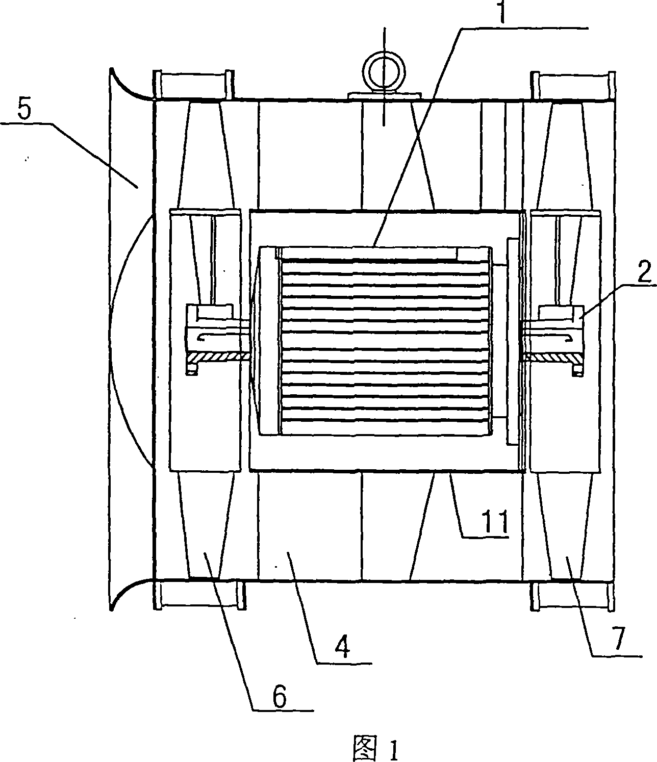
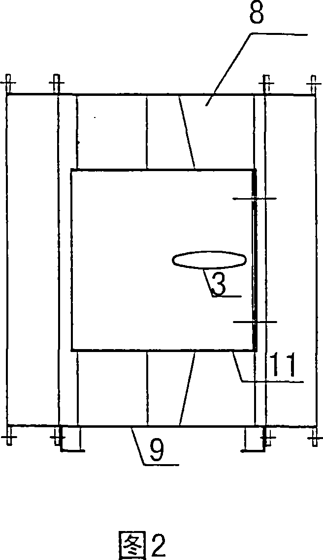
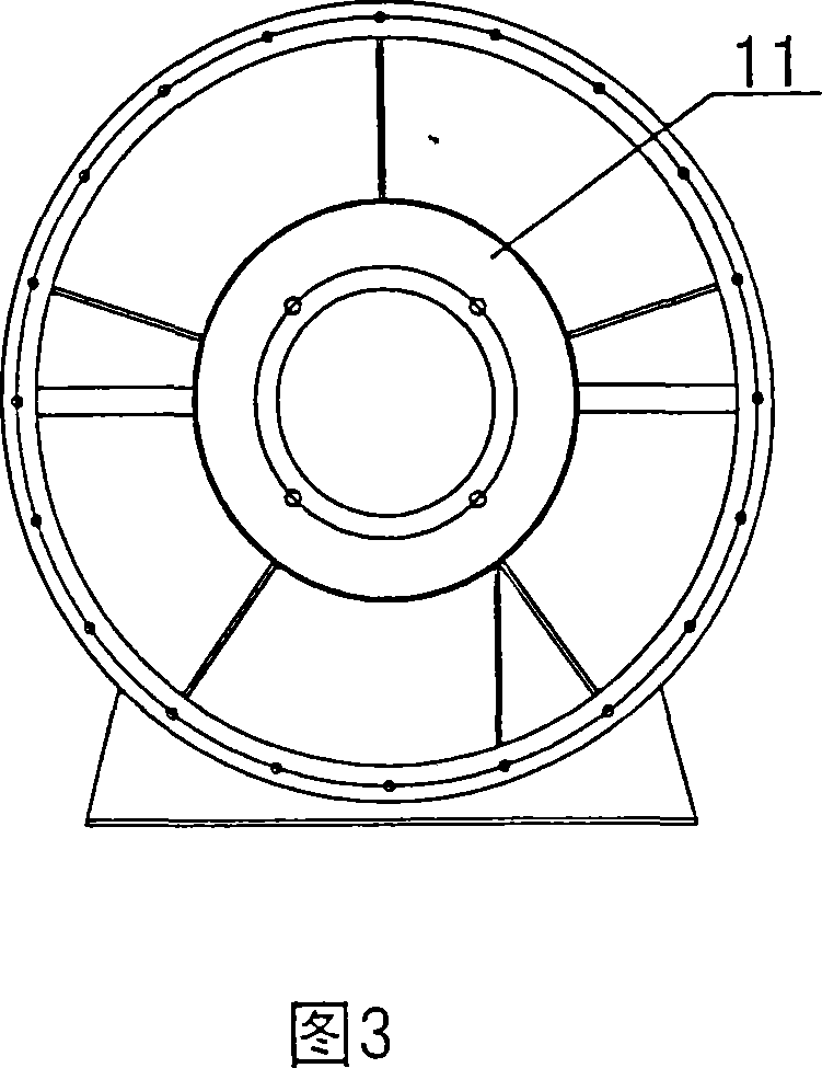
[0011] Referring to the accompanying drawings, the structure is that the shaft sleeve 2 is installed at both ends of the biaxial motor 1. The shaft sleeve 2 is tapered, and the tapered shaft sleeve has a self-locking effect, which can effectively connect the impeller and the motor shaft. Axial locking, reliable contact. The cooling pipe 3 in the cooling device is installed between the outer cylinder 9 and the middle cylinder 11. One end of the cooling pipe 3 is connected to the external environment of the motor in the middle cylinder 11, and the other end of the cooling pipe 3 is connected to the environment of the two-stage axial flow fan. The external environment of the motor refers to the airflow environment caused when the motor is cooled. The static guide vane 4 is installed behind the first-stage impeller 6, which acts as a rectifier for the first-stage impeller 6 and improves the total pressure efficiency of the whole machine. The collector 5 is installed in front of th...


PUM


Abstract

The invention is a twin-stage axial flow blower. It is characterized in that cone axile bush fixed on the two terminals of two-axle electric engine. Cooling pipe in cooling device installed between external and middle tube. One end of the pipe connects to exotic environment of electric engine in middle tube. Static guide blade fixed behind primary impeller. Current collector fixed in front of primary impeller which connects to one end of two-axle electric engine. Diode impeller connects to the other end of the engine. Stayed plate fixed between external and middle tube. Footing installed on the bottom of external tube. Because of the self-locking of cone axile bush, it can axial lock impeller and axle of electric engine effective. It can confirm concentricity of axial direction and make installment and disassembling convenience, increase assembled accuracy. Suction pressure gas flow created by revolution of diode impeller can achieve effectiveness. It has characteristics of simple structure, proper design, steady performance, low cost, denoise, and energy-saving etc.

Description

technical field [0001] The present invention relates to a two-stage axial flow fan used for cooling the variable pressure fan on the electric locomotive, effectively reducing noise and saving energy. It belongs to the technical field of ventilators. Background technique [0002] The traditional axial flow fan is rotated by a common motor, that is, a rotor motor. The axial size of the motor is large, so it determines that this series of fans has a long axial size, which wastes materials and space. It is particularly obvious in the middle, and at the same time, it also brings great difficulties to the fixing of the motor. If it is simple, the strength is not enough, and if it is complicated, it will inevitably affect the flow rate, total pressure and efficiency of the internal machine. In order to overcome the above defects, the motor adopts an external rotor motor. One end cover and the stator of the motor are stationary, and the other end cover and the rotor rotate around t...

Claims


Application Information

Patent Timeline
Patent Type & Authority Applications(China)
IPC IPC(8): F04D25/16F04D29/04F04D29/58F04D29/44F04D29/34
Inventor 陈泽民王明志
Owner 陈泽民
Why Eureka
Try Eureka