
Flow equalizing low-resistance dust dedusting system
A technology for coal-fired boilers and dust removal systems, which is applied in the fields of dust removal, uniform flow and low resistance dust removal systems, and dust removal systems in thermal power plants, can solve the problems of poor uniformity of the concentration field, increased fluid resistance, and no dust removal function. Strong exchange, reduced drag coefficient, effect of reduced drag coefficient
- Summary
- Abstract
- Description
- Claims
- Application Information
AI Technical Summary
Problems solved by technology
Method used
Image

Examples
specific Embodiment 1
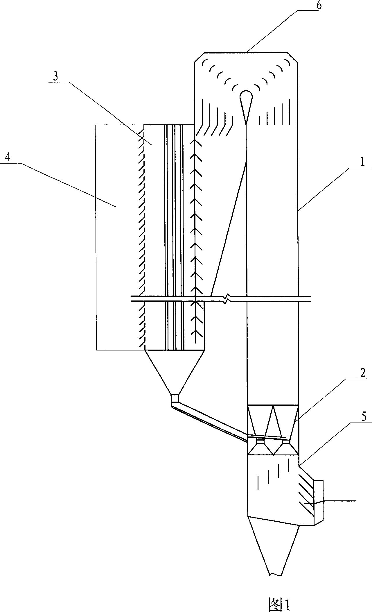
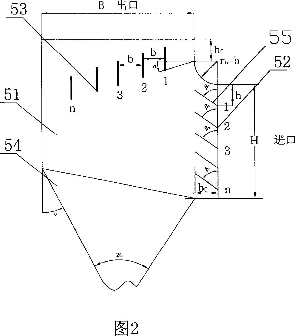
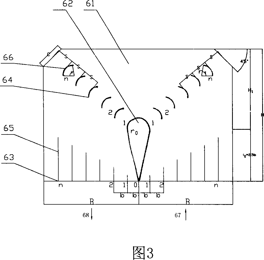
[0028] Fig. 1, Fig. 2, Fig. 3, Fig. 4 and Fig. 5 constitute specific embodiment 1 of the present invention.
[0029] Referring to Fig. 1, the present embodiment includes a flue 1, a multi-venturi tube gas distribution and recirculation material return combiner 2, an upper air inlet knuckle airflow uniform distribution smoke box 3 and a dust collector 4; the air inlet of the flue 1 A 90° sharp elbow 5 with equal flow and low resistance is provided. The air outlet of the flue 1 is equipped with a 180° sharp elbow 6 with equal flow and low resistance. Between the sharp bend 5 of 90° of resistance and the sharp bend 6 of 180° of equal flow and low resistance, the air outlet of the flue 1 is connected to the air inlet of the smoke box 3 of the upper air inlet knuckle, and the air flow of the upper air inlet knuckle is evenly distributed. The air outlet of box 3 is connected with the air inlet of dust collector 4 .
[0030] Referring to Fig. 2, the described sharp elbow 5 with equa...
specific Embodiment 2
[0036] Referring to Fig. 6 and Fig. 7, the characteristic of this specific embodiment 2 is: the dust collector 4 located at the exit of the uniformly distributed airflow smoke box 3 is composed of a ladder groove plate electrostatic precipitator, and the electric precipitator is composed of 2 to 3 rows in a staggered manner. Ladder groove plate 41, discharge electrode 42 and power supply circuit 43 arranged in columns form, the voltage output terminal of power supply circuit 43 connects discharge electrode 42, power supply circuit and grounding end connect ladder groove plate 41, constitute dust collecting pole; 41 and the discharge electrode 42 are arranged as one-to-one pairs to form an electrostatic precipitator unit. All the other are identical with specific embodiment 1.
specific Embodiment 3
[0037] The characteristics of this specific embodiment 3 are: the dust collector 4 is a bag filter, and the rest are the same as the specific example 1.
PUM
 Abstract
Description
Claims
Application Information