Three casing pipes energy accumulating solar and air resource heat pump integrated system

An air source heat pump and integrated system technology, which is applied in hot water central heating systems, heating systems, residential hot water supply systems, etc., can solve the problem that the heating capacity is not synchronized with the building load demand, and the solar heat pump has low efficiency in collecting thermal energy. , vulnerable to weather and other problems, to save high-level electric energy, improve operating results, reduce installed capacity

Inactive Publication Date: 2007-09-12
HARBIN INST OF TECH
View PDF0 Cites 41 Cited by
  • Summary
  • Abstract
  • Description
  • Claims
  • Application Information

AI Technical Summary

Problems solved by technology

[0003] The purpose of the present invention is to solve the problem that the application of the air source heat pump unit in the central air-conditioning system causes the load of the power grid to rise continuously, the heat supply capacity of the heat pump in winter is not synchronized

Method used


Image

  • Three casing pipes energy accumulating solar and air resource heat pump integrated system
  • Three casing pipes energy accumulating solar and air resource heat pump integrated system
  • Three casing pipes energy accumulating solar and air resource heat pump integrated system

Examples


specific Embodiment approach 1

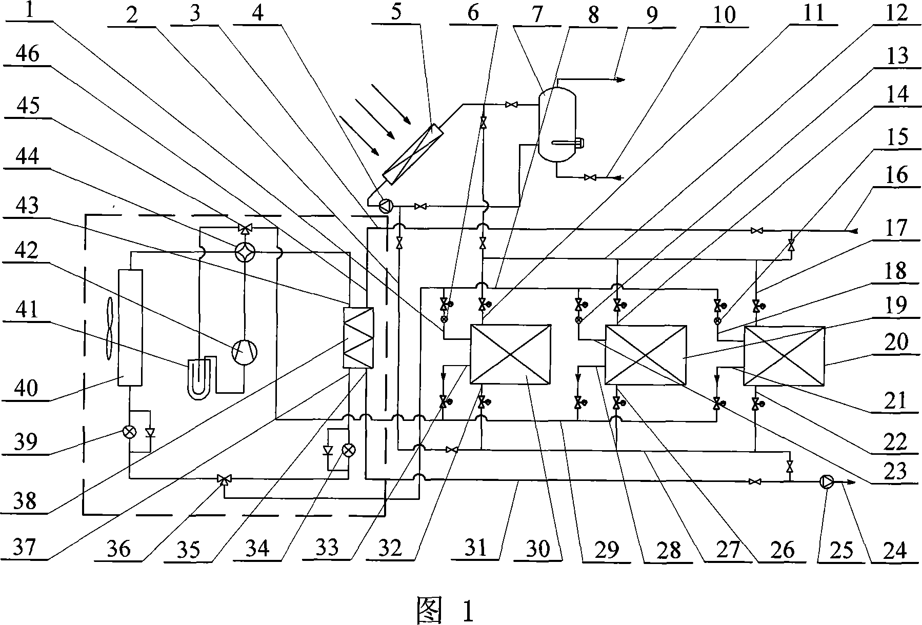
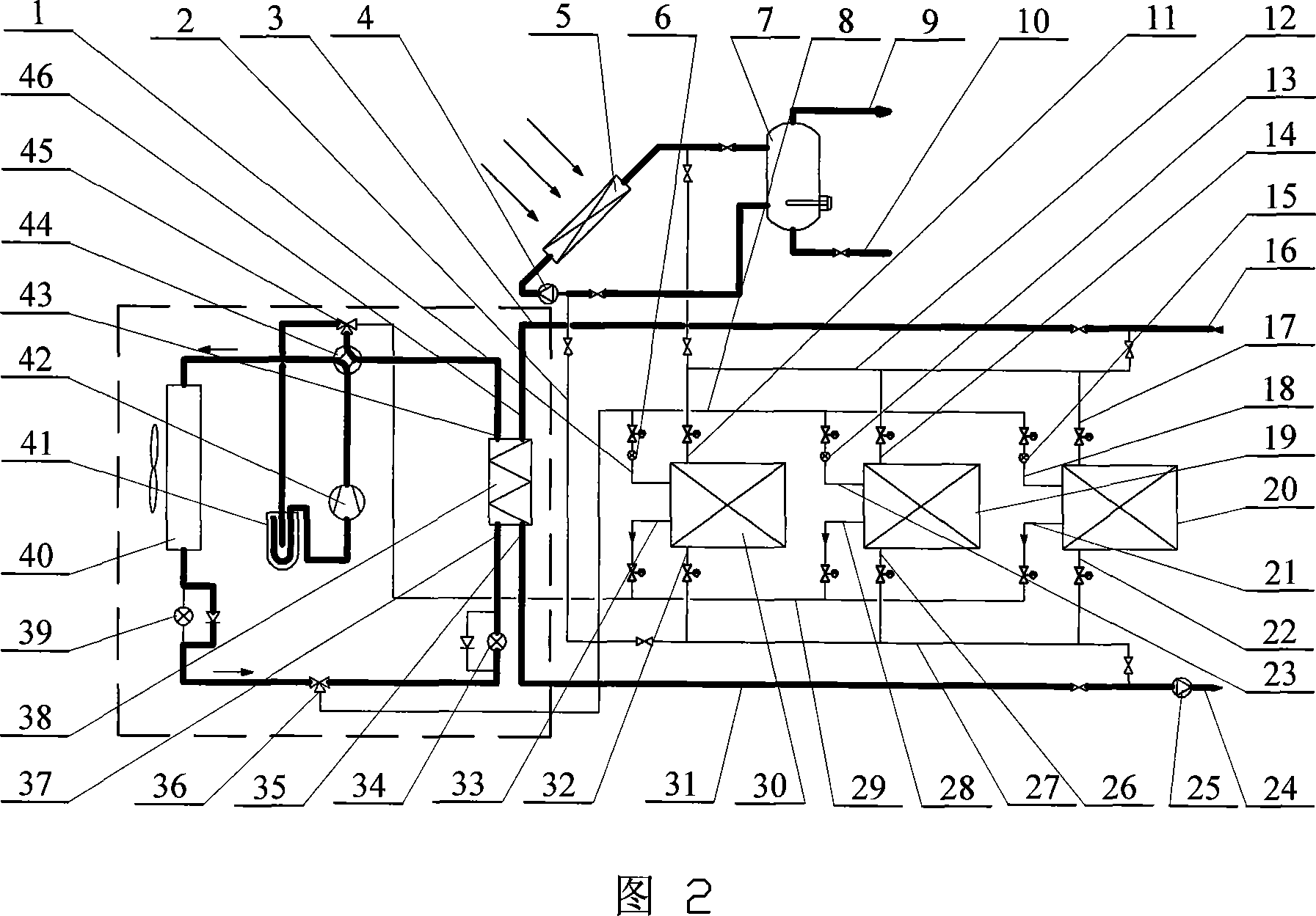
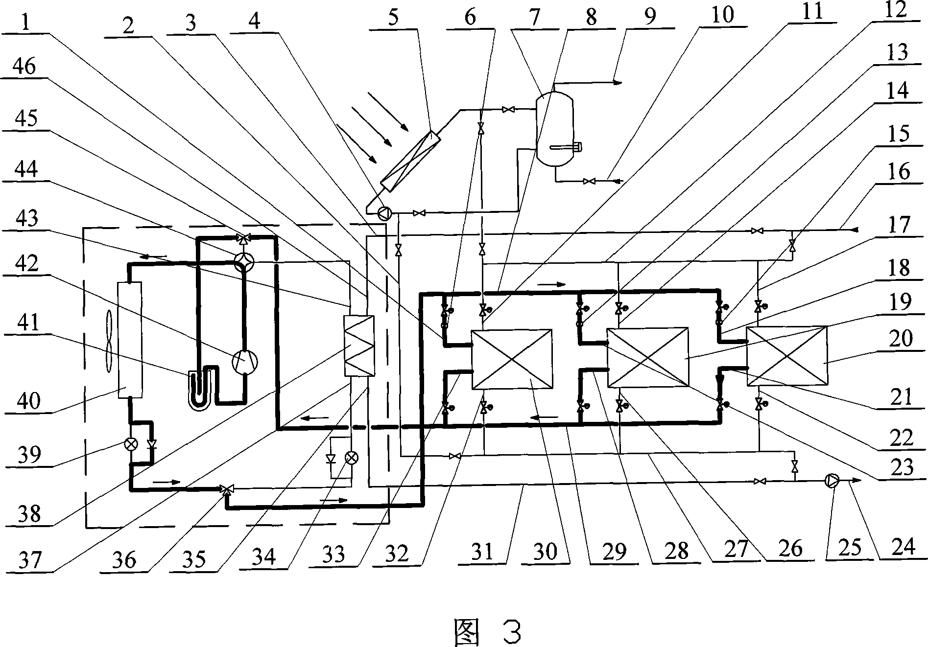
[0015]Specific embodiment one: (referring to Fig. 1~Fig. 11), this embodiment consists of the fifth pipeline 2, the circulating water pump 4, the solar heat collector 5, the first expansion valve 6, the hot water tank 7, the first pipeline 8, the first Second pipeline 12, second expansion valve 13, third expansion valve 15, second phase change material energy storage heat exchanger 19, third phase change material energy storage heat exchanger 20, third pipeline 27, fourth pipeline 29, The first phase change material energy storage heat exchanger 30, the sixth pipeline 3, the heat supply pump 25, the seventh pipeline 31, the fourth expansion valve 34, the first three-way valve 36, the first heat exchanger 38, the fifth expansion Valve 39, second heat exchanger 40, low-pressure gas-liquid separator 41, heat pump compressor 42, four-way reversing valve 44 and second three-way valve 45, the inlet of the first phase change material energy storage heat exchanger 30 The water inlet 1...

specific Embodiment approach 2

[0016] Specific embodiment two: (see Fig. 12) the first phase change material energy storage heat exchanger 30, the second phase change material energy storage heat exchanger 19 and the third phase change material energy storage heat exchanger 20 of this embodiment are respectively The water inlet pipe 51, the support body 52, the central casing 53, the first middle casing 54, the first outer casing 55, the first connecting pipe 56, the second connecting pipe 57, the second outer casing 58, The second middle layer casing 59, the third middle layer casing 60, the third outer layer casing 61, the outlet pipe 62 and the phase change material 64, the first outer layer casing 55 is arranged on the second outer layer casing 58 The upper side of the upper side, the third outer casing 61 is arranged on the lower side of the second outer casing 58, the first middle casing 54 is arranged in the first outer casing 55, and the second middle casing 59 is arranged In the second outer casing...


PUM


Abstract

The invention is a kind of system integrated by three casing pipe solar energy with energy storage and air-source heat pump, it relates to a kind of integrated system of heat pump. The aim of the invention is to settle the problem of application of air-source heat pump which makes network load rise gradually, ability of supplying heating of heat pump in winter and demanding of load of buildings not in-phase and makes efficiency of solar heat pump's collection low in the central air-conditioning system, at the same time, the cost is higher and it is often influenced by the weather. Intake of the first energy storage heat exchanger, Intake of the second energy storage heat exchanger and intake of the third energy storage heat exchanger connect with the second pipeline separately. The invention realizes electrical load's peak shifting and valley filling , balances heat pump heat-supplying load day and night in winter, adopts the running pattern of multiple heat sources which include air source, solar power and heat storage source, makes up for existing scarcity when single heat source runs, the air-condition can work at full load as much as possible. The invention can realize 5 kinds of operation patterns in summer and 4 kinds in winter.

Description

technical field [0001] The invention relates to a heat pump integrated system, in particular to a solar energy and air source integrated heat pump system with dual functions of phase change accumulators for heat storage in winter and cold storage in summer. Background technique [0002] With the increasing application of air source heat pump units, the existing problems are gradually reflected in the process of use: (1) The use of air conditioners in summer is concentrated, resulting in concentrated power loads and exacerbating the peak-to-valley difference in urban power grids. Since air conditioners are mainly operated during the daytime in summer, the load on the power grid continues to rise, resulting in a continuous increase in the peak load of the power grid. (2) The heating capacity of the heat pump in winter is not synchronized with the load demand of the building, and there is a contradiction between supply and demand. Affected by the temperature difference between...

Claims


Application Information

Patent Timeline
IPC IPC(8): F25B30/00F24D3/18F24D17/02
CPCY02B30/12
Inventor 姚杨姜益强马最良杨灵艳
Owner HARBIN INST OF TECH
Why Eureka
Try Eureka