Member for online cleaning and removing scale of heat exchange tube

A technology for heat exchange tubes and components, applied in the field of on-line cleaning and descaling of heat exchange tubes, can solve problems such as unsatisfactory cleaning and descaling effects, difficult wet diameter and specific gravity of rubber balls, and large flow resistance, etc. The effect of controllable and stable density and low flow resistance

Inactive Publication Date: 2007-09-12
TSINGHUA UNIV
View PDF0 Cites 19 Cited by
  • Summary
  • Abstract
  • Description
  • Claims
  • Application Information

AI Technical Summary

Problems solved by technology

At present, the on-line descaling in the heat exchanger tube mainly includes spiral bond/sheet descaling, reciprocating coil spring descaling and rubber ball cleaning and descaling, etc., but these descaling methods have certain deficiencies that affect their use.
Spiral bond/sheet type descaling and reciprocating coil spring descaling methods need to hang and insert descaling objects in the heat exchange tube to affect the flow channel, the flow resistance is relatively large, and at the same time, the entrained substanc

Method used


Image

  • Member for online cleaning and removing scale of heat exchange tube
  • Member for online cleaning and removing scale of heat exchange tube
  • Member for online cleaning and removing scale of heat exchange tube

Examples


Example Embodiment

[0035] Example 1:

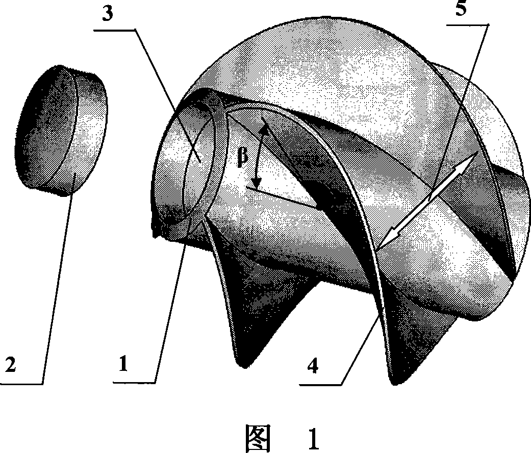
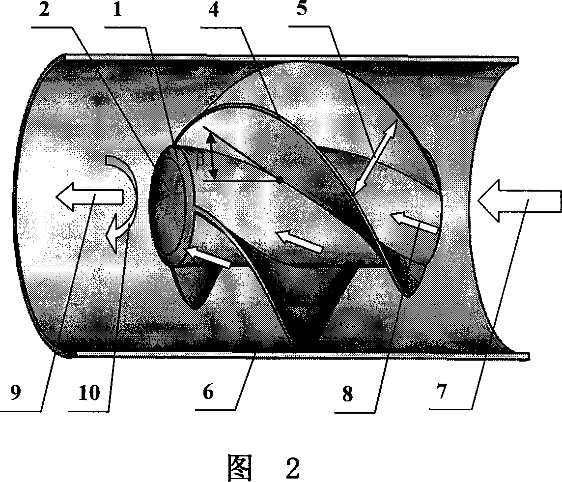
[0036] As shown in Figure 1, the present invention includes a hollow cylindrical density adjustment cavity 1. One end of the adjustment cavity 1 is closed, and the other end is sealed to connect with an end cover 2. The end cover 2 and the adjustment cavity 1 can be connected by interference fit. , It can also be connected by bonding or barb connection. The adjustment medium 3 is arranged in the cavity of the adjustment cavity 1, and four spiral blades 4 are evenly arranged on the outer circumference of the adjustment cavity 1 with the axis of the adjustment cavity 1 as the rotation axis. The helix angle of the spiral blade 4 is β, 4 The maximum outer contours of the spiral blades 4 and the adjusting cavity 1 together form an approximately spherical spherical element, and the space between the spiral blades 4 forms four spiral flow channels 5.

[0037] In this embodiment, the spiral blade 4 and the adjustment cavity 1 are made of one of the non-foam polymer mat...

Example Embodiment

[0044] Example 2:

[0045] As shown in Figure 9, the difference between this embodiment and Embodiment 1 is: the rotating shaft is a solid cylinder 17, that is, the axis of the solid cylinder 17 is the axis of rotation of the spherical cleaning and descaling element, and the axis of the solid cylinder 17 is the axis of rotation of the spherical cleaning and descaling element. Four spiral blades 18 are evenly arranged in the circumferential direction of the spiral blade 18, the spiral angle β of the spiral blade 18 is 60°, and the maximum outer contour of the four spiral blades and the solid cylinder 17 is a spherical spherical element; four spiral blades are formed between the four spiral blades. A spiral space is a spiral fluid channel. When fluid flows through the spiral channel, the spherical element of the present invention will rotate rapidly. The main material of this embodiment is non-foam rubber-butadiene rubber + styrene butadiene rubber. In order to improve or change the...

Example Embodiment

[0046] Example 3:

[0047] As shown in Fig. 10, the present invention is formed by connecting four spiral blades 19, and the connection method is one-time forming or bonding. The spiral angle β of the spiral blade is 45°, and the maximum outer contour formed by the four spiral blades 19 is Spherical spherical element, the four spiral blades 19 are evenly arranged in the circumferential direction. In this embodiment, the rotation axis of the spherical element is the symmetrical centerline of the four spiral blades, and four spiral spaces, namely spiral fluid, are formed between the four spiral blades 19 Channel, when the fluid flows through the spiral flow channel, the spherical cleaning and descaling element will produce rapid rotation. In this embodiment, the density adjustment cavity is not provided, and its density is determined by the density of the material. A suitable material can be selected to ensure that its density is relatively close to the density of the conveying flui...


PUM

PropertyMeasurementUnit
The inside diameter ofaaaaaaaaaa
Lengthaaaaaaaaaa
Wall thicknessaaaaaaaaaa

Abstract

The invention discloses an element that heat exchange tube cleans and releases contaminant; it is characterized in that it includes a global element which has some. Roundness space of global element are separated by screwing or inclining heave to form the flow passages; The change of the global element's external diameter due to immergence is smaller than 2%, The of due to immergence is smaller than 5%, the error of the global element's density and transporting fluid's density is smaller than 10%. The most biggest outer contour of the element cleaning and releasing contaminant appears spherical or elliptical or appears approximate, possesses flow passages screwing or inclining to a rotating axis, when fluid flows in the flow passage, it drives the global element at liberty in the heat exchange tube prepared for cleaning and releasing contaminant. Therefore it has the characteristics in that the cleanout is effectual, flowing resistance is small and not apt to jam the heat exchange tube.

Description

technical field [0001] The invention relates to a cleaning and descaling element, in particular to an on-line cleaning and descaling element for heat exchange tubes which uses fluid motion as power to clean the heat exchange tubes. Background technique [0002] Shell-and-tube heat exchangers are widely used in electric power, chemical industry, petroleum and other industrial fields. Most of the heat exchangers have fouling and scaling during operation, especially the condensers cooled by circulating water. , water cooler, etc. The fouling and scaling of the heat exchanger will reduce the heat transfer coefficient of the equipment, increase the energy consumption, and even cause the equipment to fail to operate normally due to pipe blockage; scaling will also form corrosion under the scale and shorten the service life of the equipment. At present, there are online and off-line methods for cleaning and descaling in the heat exchange tubes of shell-and-tube heat exchangers. On...

Claims


Application Information

Patent Timeline
IPC IPC(8): F28G1/12
Inventor 孟继安
Owner TSINGHUA UNIV
Why Eureka
Try Eureka