Mechanical vision locating method

A positioning method and machine vision technology, applied in the fields of instrumentation, photogrammetry/video surveying, surveying and navigation, etc., can solve the problems of accurate analysis of local parts of interest, insufficient detection accuracy, increased equipment cost, etc. Similarity, low cost, and improved detection accuracy

Inactive Publication Date: 2007-09-12
HUAZHONG UNIV OF SCI & TECH
View PDF2 Cites 34 Cited by
  • Summary
  • Abstract
  • Description
  • Claims
  • Application Information

AI Technical Summary

Problems solved by technology

[0004] At present, research on the measurement or detection of planar objects basically uses a camera, such as the planar measurement method based on a single image in Chinese patent documents (its publication number is CN1427245, and the publication date is 2003.07.02) and the single-view method based on parallel lines Plane measurement method (its public number is CN1427246, and the public date is 2003.07.02), but because the camera needs to detect a larger area, when it is necessary to accurately observe some local interested parts of the entire area and real-time monitor these parts When performing necessary processing, such as more detailed detection and soldering of circuit board solder joints, a high-quality camera is required, otherwise it will be impossible to accurately analyze local interested parts, which will inevitably increase the cost of the equipment
[0005] Existing machine vision applications in the industry, either the detection accuracy is not high enough, or the cost of equipment is increased in order to achieve high precision
At present, the industry mainly uses a high-quality camera to detect the products on the assembly line, so the whole set of equipment is more expensive

Method used


Image

  • Mechanical vision locating method
  • Mechanical vision locating method
  • Mechanical vision locating method

Examples


Embodiment Construction

[0019] The basic principle of the present invention is: use two cameras, wherein, the long-distance camera processes the target object as a whole, shoots the global image of the target object, and detects the interesting part on the captured global image (depending on the needs of the application) ); and then control the manipulator to move the close-range camera to these parts of interest, and take high-precision images for further detailed detection and analysis.

[0020] The technical solutions of the present invention will be further described in detail below in conjunction with the accompanying drawings and examples.

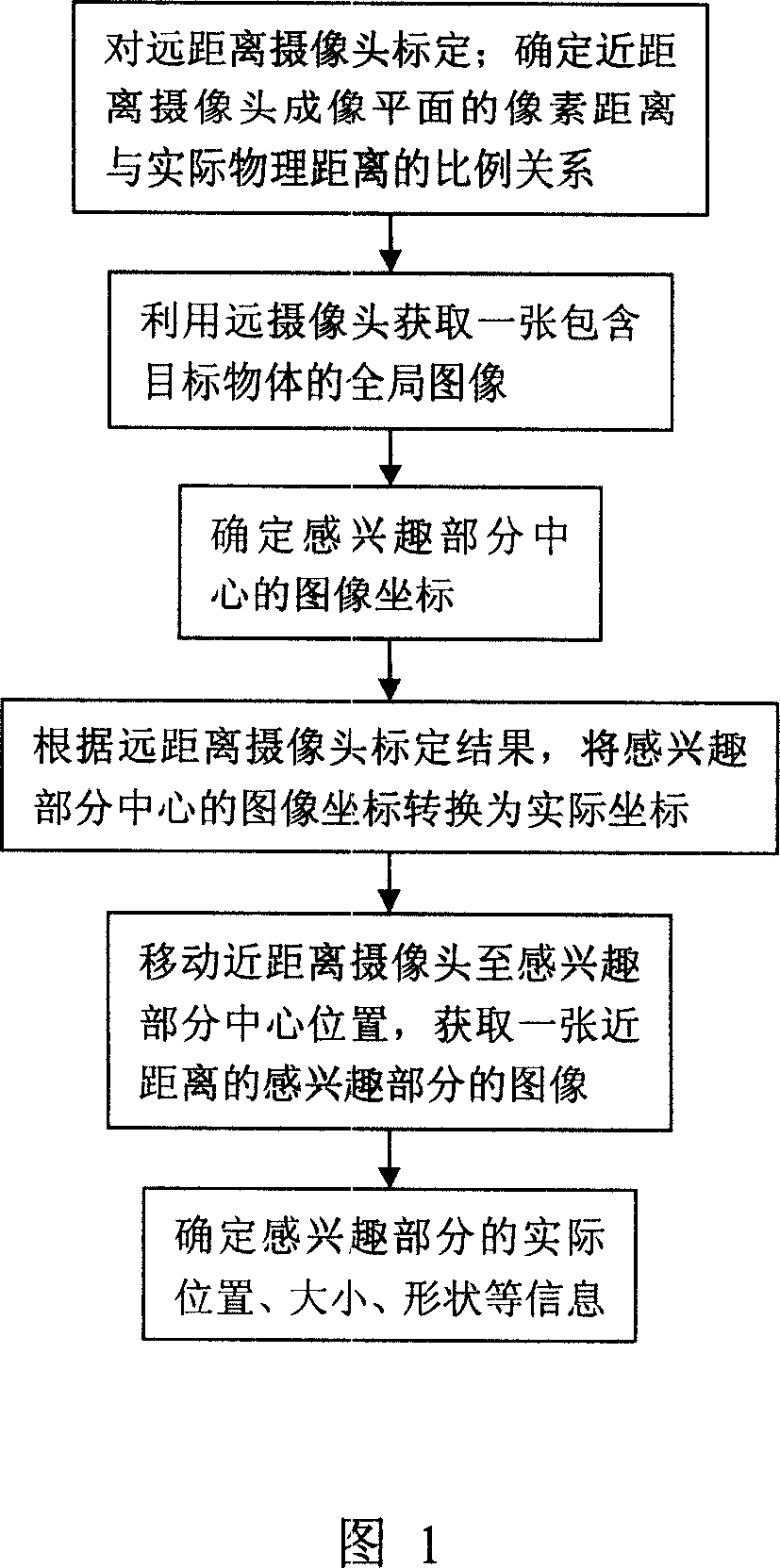
[0021] As shown in Figure 1, the machine vision positioning method of the present invention comprises the following steps:

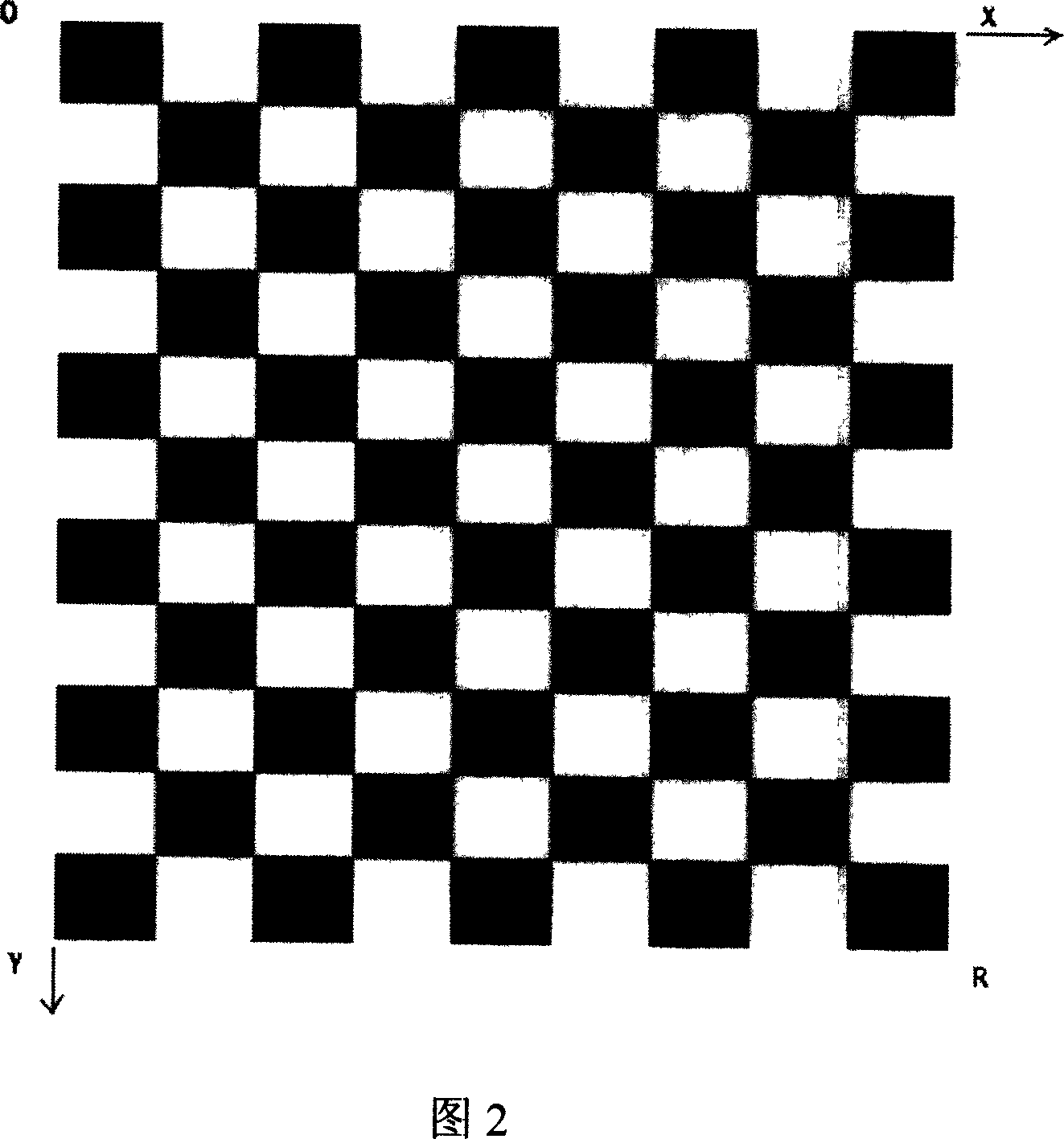
[0022] (1) Calibrate the long-distance camera, determine the corresponding coordinate transformation relationship between its imaging plane and the measured target plane; and determine the proportional relationship between the pixel d...


PUM


Abstract

This invention discloses a machine vision positioning method. It completes the detected mission by using two ordinary cameras includes remote camera used for shooting the whole image of the target object and the close camera used for shooting the interested site in short distance. Firstly calibrate remote camera and then determine the proportion relations between the distance of the actual physical distance and the close camera imaging plane pixel. By using the remote camera shoot target object image and then determine the imaged and the actual coordinates of interested center site. Move the close camera to the interested center site by using the manipulator, acquire the image and determine its imaged coordinates and the actual coordinates, get the information of actual location, shape, size in this site. This invention uses two ordinary camera to obtain with high-precision the detail information on the partial interested site of the target objects, satisfies the high precision demand on the industrial machine vision applications with low cost.

Description

technical field [0001] The invention belongs to the application field of machine vision in industry, and specifically relates to a machine vision positioning method, which utilizes two ordinary cameras to obtain detailed information of local interest parts of a target object in a large scene with high precision, such as accurate line segment Length, specific location of solder joints, etc. Background technique [0002] In modern industrial automation production, more and more machine vision technology is applied, involving various inspection, measurement and processing, such as laser engraving, printed circuit board pin welding, laser drilling, trademark cutting, etc. What these applications have in common is the need for continuous mass production and high requirements for product quality. This kind of work is highly repetitive and is usually done by manual inspection. [0003] If this process is completed simply by increasing the number of testing workers, it will inevit...

Claims


Application Information

Patent Timeline
Patent Type & Authority Applications(China)
IPC IPC(8): G01C11/00
Inventor 刘宏宋恩民刘晶晶李国宽
Owner HUAZHONG UNIV OF SCI & TECH
Why Eureka
Try Eureka