Device for limiting current of the resistive type with a strip-shaped high TC superconductor

A current-limiting device and superconductor technology, applied in superconducting devices, devices and circuits that can be switched between superconducting and normal conducting states, can solve problems such as buffer layer breakdown

Inactive Publication Date: 2007-09-12
SIEMENS AG
View PDF4 Cites 3 Cited by
  • Summary
  • Abstract
  • Description
  • Claims
  • Application Information

AI Technical Summary

Problems solved by technology

In this structure there is a risk of e

Method used


Image

  • Device for limiting current of the resistive type with a strip-shaped high TC superconductor

Examples


Embodiment Construction

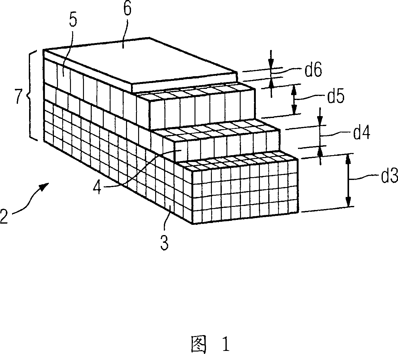
[0019] The strip conductors shown generally at 2 in FIG. 1 are based on the per se known embodiment of so-called YBCO strip conductors or “YBCO-coated conductors”. In this figure:

[0020] 3 denotes a substrate strip consisting of a normally conductive substrate metal of thickness d3,

[0021] 4 denotes at least one buffer layer of a special oxidized buffer material with a thickness d4 arranged on the substrate strip,

[0022] 5 represents the HTS layer composed of YBCO with a thickness of d5,

[0023] 6 denotes a protective layer consisting of a normally conductive protective layer metal of thickness d6, which serves as a protective or contact layer, and

[0024] 7 represents a conductor structure composed of the above four parts.

[0025] Here, the above parts can be built as follows:

[0026] - the metal substrate strip 3 is made of nickel, a nickel alloy or special steel, the thickness d3 of which is approximately 50 to 250 μm,

[0027] - at least one buffer layer or ...


PUM


Abstract

The resistive current limiting device comprises a strip-shaped superconductor (2) whose conductor structure (7) contains: at least one metallic substrate strip (3), a layer (5) made of oxidic high Tc superconducting material of the AB2Cu3Ox type; an oxidic buffer layer (4), which is arranged therebetween and which has adapted crystalline dimensions, and; a normal-conductive top layer (6) that is applied to the superconductive layer (5). The buffer layer (4) should be formed so that a transition resistance of no greater than 10<-3> Omega.cm<2> is formed at least in partial areas between the superconductive layer (5) and the substrate strip (3). For example, suitable materials are of the La-Mn-O or Sr-Ru-O or La-Ni-O or In-Sn-O type.

Description

technical field [0001] The invention relates to a superconducting resistance current limiting device with a conductor path (Leiterbahn) composed of a strip-shaped superconductor, the conductor structure of which comprises: at least one substrate strip composed of a conventionally conductive substrate metal; by AB 2 Cu 3 o x Type of Oxide High T c (Critical Temperature) A superconducting layer of a superconducting material, where A is at least one rare earth metal including yttrium, and B is at least one alkaline earth metal; composed of an oxide buffer material of appropriate crystal size, set at A buffer layer between the former two; and a normally conductive protective layer covering the superconducting layer and composed of a material with normal conductivity. A comparable flow limiting device is found in DE 199 09 266 A1. Background technique [0002] Since 1986, the high critical temperature T of more than 77K c Superconducting metal oxides are well known, which a...

Claims


Application Information

Patent Timeline
IPC IPC(8): H01L39/16
CPCH01L39/16H01L39/2461H10N60/30H10N60/0632
Inventor 汉斯-彼得·克雷默沃尔夫冈·施密特
Owner SIEMENS AG
Why Eureka
Try Eureka