
Typeset apparatus and porous printing apparatus

A technology for printing cylinders and plates, applied in stencil printing equipment, printing, printing presses, etc., can solve the problems of unstable movement, winding, and it is difficult to completely eliminate winding, and achieve the effect of simple structure and cheap structure

Inactive Publication Date: 2010-05-26
RISO KAGAKU CORP
View PDF4 Cites 0 Cited by
  • Summary
  • Abstract
  • Description
  • Claims
  • Application Information

AI Technical Summary

Problems solved by technology

[0020] However, in Patent Document 3, it is also difficult to completely eliminate the winding of the used printing plate to the pair of layout rollers, and there is a problem that the end portion of the used printing plate released from the gripper is rebounded by the rotating layout roller. , the action becomes unstable, and only one side of the printing plate is not clamped in the pair of composing rollers, so that the printing plate is wound onto the pair of composing rollers
In the case of discharging such a high-strength printing plate with the typesetting device described in Patent Document 3 (Japanese Patent Laid-Open No. 2004-195873), the end portion of the high-strength printing plate flies into the rotating pair of typesetting rollers, so , compared with the case of a low-strength printing plate, the end of the printing plate will be rebounded more and become unstable, causing the problem of winding to the typesetting roller pair

Method used


Image

  • Typeset apparatus and porous printing apparatus
  • Typeset apparatus and porous printing apparatus
  • Typeset apparatus and porous printing apparatus

Examples


no. 1 approach

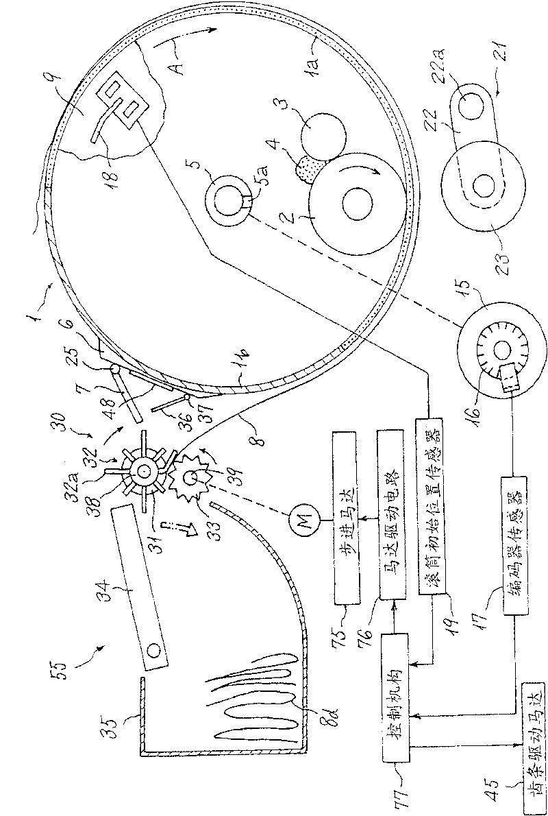
[0053] refer to Figure 1 to Figure 11 The first embodiment of the present invention will be described.

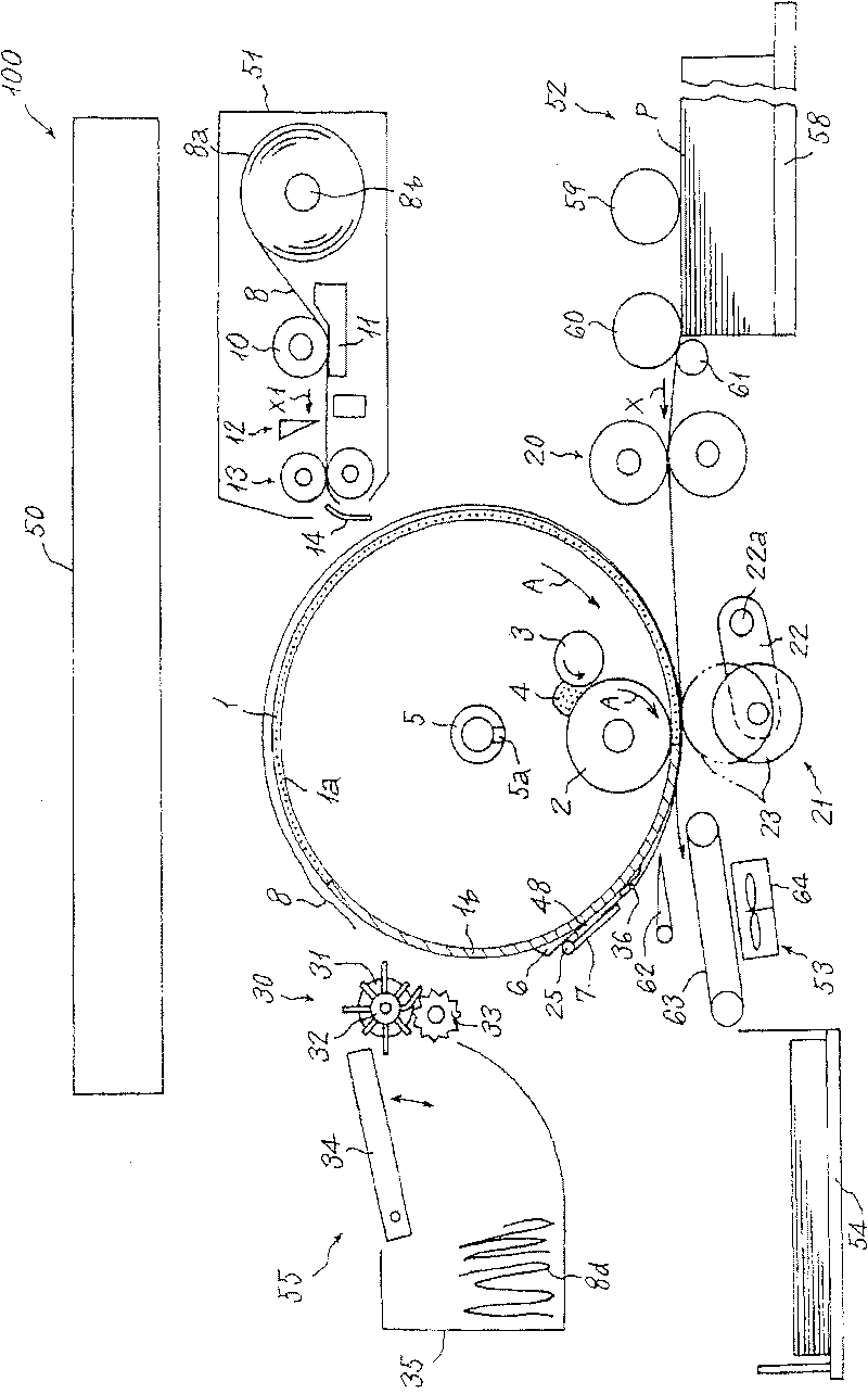
[0054] First, refer to figure 1 The configuration of the stencil printing apparatus 100 of this embodiment will be briefly described. The stencil printing device 100 includes an image reading device (scanning device) 50, a plate making device 51, a paper feeding device 52, a printing cylinder 1, a paper discharge transport device 53, a paper discharge tray 54 as a paper discharge table, a typesetting device 55, and the like. The image reading device (scanning device) 50 reads an image of an unillustrated document, and has a known configuration. The plate making device 51 makes a plate 8 and supplies plates based on image information read by the image reading device 50 or image information input from an externally connected device such as a personal computer (not shown). The paper feeding device 52 supplies printing paper P (hereinafter referred to as “paper P”) on a pap...


PUM


Abstract

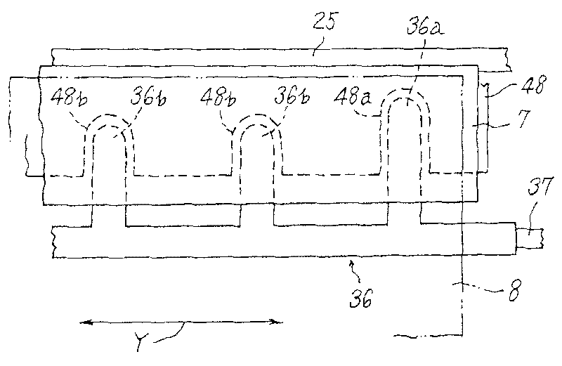
The invention provides a novel composing device and a porous printing device having the novel composing device, formes with any strength desquamated from a printing roller are capable of being prevented from winding on a composing roll pair, and being prevented from winding on the composing roll pair by a simple and low-cost structure. Shapes of elastic blades (32a) of a blade roller (32) of the composing roll pair, lengths of the plurality of the elastic blades (32a) extended from roller base portions (32b) towards centrifugal directions, are different from one another in a circle direction of the blade roller (32), and are same at an axes direction of a rotation axes (38), i.e., ends of the elastic blades (32a) are aligned at the rotation axes direction.

Description

technical field [0001] The present invention relates to a typesetting device for discharging a used printing plate, which is also called stencil base paper wound on the outer peripheral surface of a printing cylinder, and a stencil printing device provided with the typesetting device. Background technique [0002] Conventionally, there is known a heat-sensitive digital stencil printing device in which a printing plate made by heating perforation is wound on the outer peripheral surface of a freely rotating printing plate cylinder, and ink is supplied by an ink supply mechanism provided inside the printing plate cylinder. , the printing paper (hereinafter referred to as "paper") is continuously pressed on the printing plate after plate making on the printing plate cylinder by using a pressing mechanism such as a pressing roller or a pressing roller with a diameter approximately the same as that of the printing plate cylinder, and makes the ink flow from the printing plate cyli...

Claims


Application Information

Patent Timeline
Patent Type & Authority Patents(China)
IPC IPC(8): B41L13/14B41L13/10B41F27/12
Inventor 椿健悟
Owner RISO KAGAKU CORP
Learn More