
Combined piston ring with novel locating device and manufacturing method thereof

A technology of positioning device and piston ring, applied in the field of piston ring, can solve the problems of increased piston temperature, large damage of piston ring, low life of piston ring, etc., and achieve the effects of prolonging service life, preventing radial leakage and low processing cost

Inactive Publication Date: 2007-09-19
何俊明
View PDF1 Cites 11 Cited by
  • Summary
  • Abstract
  • Description
  • Claims
  • Application Information

AI Technical Summary

Problems solved by technology

In addition, in the structure of the positioning and sealing combined piston gas ring in Chinese patent ZL200420033278, due to the insufficient dislocation length of the openings of the upper and lower rings and the lack of a sealing device on the upper ring, high-pressure and high-temperature gas will be strung in to increase the temperature of the piston.
Therefore, the positioning device of the combined piston ring in the prior art is not only complicated in the processing process, but also causes great damage to the piston ring, which makes the life of the piston ring low and high in cost, and affects the working state of the cylinder.

Method used


Image

  • Combined piston ring with novel locating device and manufacturing method thereof
  • Combined piston ring with novel locating device and manufacturing method thereof
  • Combined piston ring with novel locating device and manufacturing method thereof

Examples


Embodiment 1

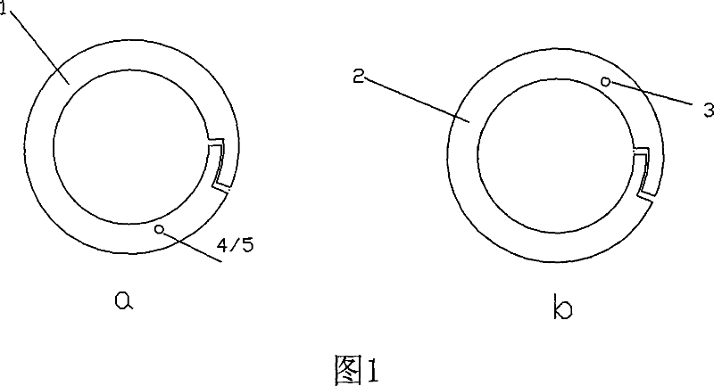
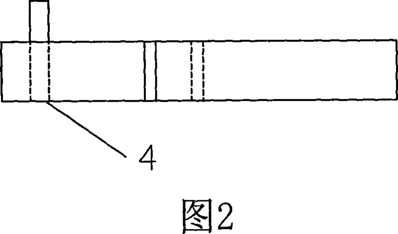
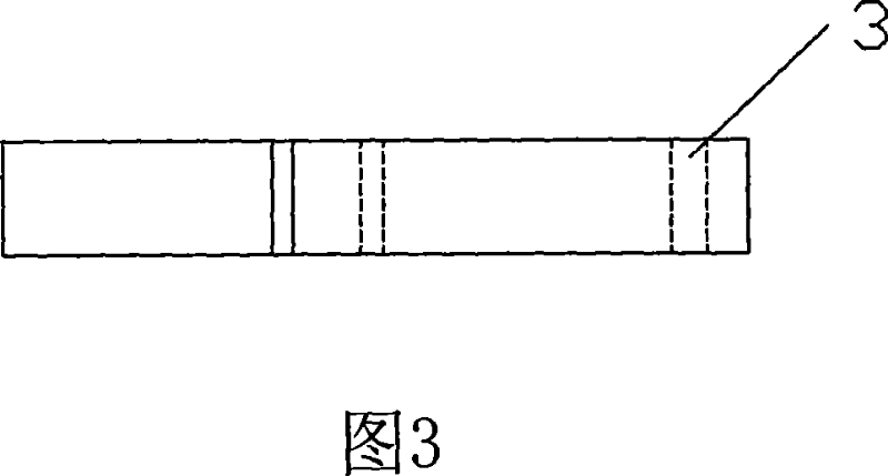
[0029] Fig. 1 is a structural schematic diagram of the first embodiment of the combined piston ring with the new positioning device according to the present invention; the two component rings are radial overlapping rings, as shown in the figure, a is the piston ring with the new positioning device of the present invention The upper component ring 1 of the combined piston ring is processed with a circular positioning pin connection hole 4 on the ring plane within the range of an angle of 90° with the port relative to the center of the piston ring. The optimal angle is less than or equal to 30°. The present embodiment is 30° to ensure that the positioning pin connecting hole 4 does not bear a large moment, and the diameter of the positioning pin connecting hole 4 is 0.9mm; b is the lower component ring 2 of the combined piston ring with a new positioning device in the present invention, A circular positioning groove 3 is processed on the ring plane within the range of 90° include...

Embodiment 2

[0031]Fig. 4 is a structural schematic diagram of the second embodiment of the combined piston ring with a new positioning device according to the present invention; Together they form a positioning cutout 6, which passes through the inner edge of the piston ring and is arc-shaped with a radial width of 1.4mm. A circular positioning pin connection hole 4 with a diameter of 0.9mm is processed on the ring forming an angle of 30° with the port relative to the center of the piston ring. The part where the positioning pin 5 is inserted into the positioning pin connection hole 4 is cylindrical, and the cross section of the positioning part It is arc-shaped and matches with the positioning notch 6. The arc length of the positioning notch 6 is greater than the arc length of the positioning pin 5. The positioning pin of this structure not only plays the role of positioning but also plays the role of sealing sealing piece; the positioning pin connecting hole 4 and the Corresponding to t...


PUM


Abstract

The invention discloses a combined piston ring having new type positioning device and manufacturing method thereof, comprising upper composing ring and lower composing ring and positioning device for positioning the two composing rings. The positioning device includes a positioning pin, positioning slot, and also a positioning pin jointing hole provided between inner edge and outer edge of the upper composing ring or lower composing ring, the positioning pin is closely jointed with one ring through the hole, which is then inserted to positioning slot of another composing ring, the upper composing ring and the lower composing ring are positioned and assembled, ports of the upper composing ring and the lower composing ring are interlaced. Positioning slot of the combined piston ring and the positioning pin jointing hole are formed by pulse laser processing. Positioning device of the invention does not damage the inner and outer edges of the piston ring, ring surface finish and flatness will not be destroyed, which can be provided on any position of the ring surface, processing of the device is easy, and cost is low, which can prolong using lives of the cylinder and the piston ring.

Description

technical field [0001] The invention relates to a piston ring, in particular to a combined piston ring with a novel positioning device, and also to a manufacturing method of the piston ring. Background technique [0002] In the prior art, for some internal combustion engine piston rings, only one single ring is installed in each piston ring groove, and the openings of the multi-channel air rings are misplaced and installed with each other. When the piston ring internal combustion engine is working, there is always axial air leakage at the ring opening and radial air leakage channels, and with the wear of the piston ring, the ring opening becomes larger and larger, and its air leakage channels will gradually increase, resulting in insufficient power of the internal combustion engine, waste of fuel, high noise and serious carbon deposition; The structure of double-piece piston rings is installed in the piston ring groove. When installing, the ports of the two piston rings are ...

Claims


Application Information

Patent Timeline
Patent Type & Authority Applications(China)
IPC IPC(8): F02F5/00F16J9/14
Inventor 何俊明
Owner 何俊明
Learn More