Method for obtaining transceiver channel transmission time of user terminal

A user terminal and transceiver channel technology, applied in the field of obtaining the transmission time of the user terminal transceiver channel and time delay testing, can solve the problems of high integration of the user terminal, measurement of the transmission time of the transceiver channel, measurement of the transmission time of the transmission channel, etc., to reduce positioning. the effect of error

Active Publication Date: 2007-09-19
LEADCORE TECH
View PDF0 Cites 27 Cited by
  • Summary
  • Abstract
  • Description
  • Claims
  • Application Information

AI Technical Summary

Problems solved by technology

Although the transmission time of the module under test can be measured by a network analyzer at present, the limitation of using a network analyzer to measure the transmission time is that the input and output frequencies of the module under test must be the same. However, due to the high integration of the user terminal, in order to reduce the user The design indicators of each component of the terminal, the receiving channel adopts a zero-IF scheme, that is, the receiving channel converts the received signal into a zero-hertz signal. It is not possible to measure the transmission time of the entire transceiver channel with a network analyzer
Due to the high integration level of the user terminal, it is also impossible to use a network analyzer to measure the transmission time of the transmission channel alone, that is, the transmission time between the analog baseband signal or the digital baseband signal after the digital-to-analog converter (DAC) and the radio frequency signal, and The transit time of the receive channel, i.e. the transit time from the RF signal to the analog baseband signal or the digital baseband signal after the analog-to-digital converter (ADC), cannot be measured separately with a network analyzer
[0008] In addition, although the transmission time of the user terminal transceiver channel can be estimated by the transmission time index given in the device data, the transmission time obtained in this way is very rough, and only a compromise method can be used for estimation, and the obtained The transfer time is not the transfer time of each device when it is actually working
If the transmission time caused by the printed circuit between each component is introduced, the estimation becomes extremely difficult

Method used


Image

  • Method for obtaining transceiver channel transmission time of user terminal
  • Method for obtaining transceiver channel transmission time of user terminal
  • Method for obtaining transceiver channel transmission time of user terminal

Examples


Embodiment Construction

[0029] In order to make the object, technical solution and advantages of the present invention clearer, the present invention will be further described in detail below in conjunction with the accompanying drawings.

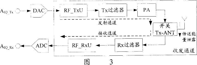
[0030] In the present invention, the transmission time of the transceiver channel is obtained by performing a self-loop test on the user terminal. The specific implementation steps of the present invention will be described in detail below in conjunction with FIG. 3 .

[0031] Step 1: Set the physical layer of the user terminal to be tested to support the self-loop test. For example, burn the physical layer of the user terminal into a physical layer that supports the self-loop test, or add a test module to the user terminal. After starting the test module, The test module sets the physical layer as the physical layer supporting the self-loop test; all test programs can communicate with the physical layer supporting the self-loop test. The self-loop test means that...


PUM


Abstract

The invention discloses a method for obtaining the user terminal transceiving channel transmission time. The physical layer of the user terminal is set to support loop back testing. The switch is set on the emission state by the user terminal. The transmitter channel and receiving channel are in working state at the same time. The transmitter channel of the user terminal sends IQ signal according to the timing reference of the physic layer and records the time which is relative to the time when the timing reference sends the IQ signal. The IQ signal, which is released from the switch, is received by the receiving channel and processed with a physical layer synchronous algorithm to obtain the time of the IQ signal which is relative to the timing reference. The user terminal transceiving channel transmission time is obtained by comparing the time when the IQ signal is sent with the time when the IQ signal is received. The invention obtains the accurate transceiving channel transmission time via the loop back testing on the user terminal, furthermore the time initial lead which is obtained by the user terminal by using the antenna aperture as the reference can be corrected via the transmission time.

Description

technical field [0001] The invention relates to a time delay testing technology in the communication field, in particular to a method for obtaining the transmission time of a receiving and sending channel of a user terminal. Background technique [0002] In a Time Division Duplex (TDD, Time Division Duplex) mobile communication system, strict synchronization is required for both the uplink and the downlink. During the process from turning on the user terminal to entering the idle mode, the user terminal only establishes downlink synchronization with the base station, and the user terminal does not know the distance to the base station at this time. During the random access process, the user terminal establishes uplink synchronization with the base station, that is, the base station requires that uplink signals sent by different user terminals at different distances arrive synchronously. For the TDD mobile communication system, uplink synchronization can bring great benefits...

Claims


Application Information

Patent Timeline
Patent Type & Authority Applications(China)
IPC IPC(8): H04J3/06H04L12/26
Inventor 林代娟樊锋邹勇
Owner LEADCORE TECH
Why Eureka
Try Eureka