Image encoding apparatus, image decoding apparatus and control method therefor
An image coding and coding technology, which is applied in image coding, image communication, image data processing and other directions, can solve the problem of increasing the k parameter, and achieve the effect of good compression performance
- Summary
- Abstract
- Description
- Claims
- Application Information
AI Technical Summary
Problems solved by technology
Method used
Image

Examples
no. 1 Embodiment approach
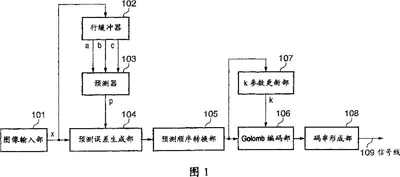
[0104] FIG. 1 is a block configuration diagram showing a functional configuration of an image processing apparatus according to the present embodiment.
[0105] As shown in FIG. 1 , the image processing apparatus for performing image encoding according to the present embodiment includes an image input unit 101 , a line buffer 102 , a predictor 103 , a prediction error generation unit 104 , and a prediction order conversion unit 105 , a Golomb coding unit 106 , a k parameter updating unit 107 , and a code string forming unit 108 . In FIG. 1, 109 denotes a signal line.
[0106] Hereinafter, the image encoding process performed by the image processing apparatus according to the present embodiment will be described with reference to FIG. 1 . Here, the encoding target image is taken as monochrome image data in which each pixel is composed of 8-bit (range of 0 to 255) pixel data representing a luminance value or a density value. However, this method can also be applied to a color ...
no. 2 Embodiment approach
[0176] Next, the second embodiment will be described. In the image processing apparatus according to the first embodiment, correction is performed by increasing or decreasing the encoding parameter k every time the symbol to be encoded is outside the optimum symbol range. In such a case, there is an advantage of being able to quickly respond to changes in the statistical properties of information sources, but stability becomes a problem in information sources whose properties change little.
[0177] For example, consider the probability distribution f(n,k)=(1 / 2)^L(n,k) in which the coding efficiency is the largest among the respective k parameters. L(n, k) is the code length when Golomb coding is performed on the coding target symbol n with the coding parameter k, and is given by L(n, k)=k+1+floor(n / (2^k)). x^y represents x raised to the y power, and floor(x) represents a function that returns the largest integer not exceeding x.
[0178] FIG. 7 shows the probability distrib...
no. 3 Embodiment approach
[0214] In the above-described second embodiment, the method of reducing the k parameter when the symbol of the secondary region 51 occurs has been described, but the number of occurrences of the update may be changed according to the k parameter. An example of this will be described as the third embodiment.
[0215] The block diagram of the image processing apparatus according to the third embodiment is the same as that of FIG. 10 described in the second embodiment, and only the processing performed by the k-parameter updating unit 1002 is different. Hereinafter, the processing of the k-parameter updating unit 1002 in the third embodiment will be described.
[0216] The k parameter update unit 1002 of the third embodiment holds the correspondence table between the index value i and the parameter k shown in FIG. 12 , and the array I storing the index value i for the 365 state numbers S classified by the context generation unit 1001 [S]. All elements of the array I[S] are set ...
PUM
 Abstract
Description
Claims
Application Information
 - R&D
- Intellectual Property
- Life Sciences
- Materials
- Tech Scout
- Unparalleled Data Quality
- Higher Quality Content
- 60% Fewer Hallucinations
Browse by: Latest US Patents, China's latest patents, Technical Efficacy Thesaurus, Application Domain, Technology Topic, Popular Technical Reports.
© 2025 PatSnap. All rights reserved.Legal|Privacy policy|Modern Slavery Act Transparency Statement|Sitemap|About US| Contact US: help@patsnap.com