X-ray attenuation correction method, image generating apparatus, x-ray ct apparatus, and image generating method
一种产生装置、衰减校正的技术,应用在X射线CT装置,图像产生领域,能够解决降低断层扫描图像等问题,达到散射X射线校正精确、减轻X射线衰减的效果
- Summary
- Abstract
- Description
- Claims
- Application Information
AI Technical Summary
Problems solved by technology
Method used
Image
Examples
no. 1 example
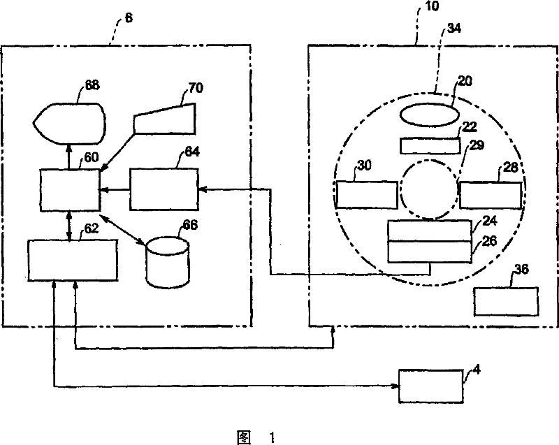
[0061] An overview of an X-ray CT apparatus according to a first preferred embodiment of the present invention will now be described. Referring now to FIG. 1 , there is shown a schematic block diagram of an X-ray CT apparatus. As shown in FIG. 1 , the device includes a scanning frame 10 , an operation console 6 and an imaging table 4 .
[0062] The gantry 10 includes an X-ray tube 20 . Not shown in the figure but the X-ray emitted from the X-ray tube 20 as the X-ray generator is passed through a fan-shaped collimator 22 having a certain thickness, for example, to form an X-ray cone beam, and will be transmitted to the surface. An X-ray detector 24 placed against the X-ray tube 20 .
[0063] The X-ray detector 24 has a plurality of scintillator arrays arranged in a matrix in the developing direction of the fan beam X-rays. The X-ray detector 24 is a multi-channel detector with multiple scintillators arranged in a matrix structure with a certain width.
[0064] The X-ray det...
no. 2 example
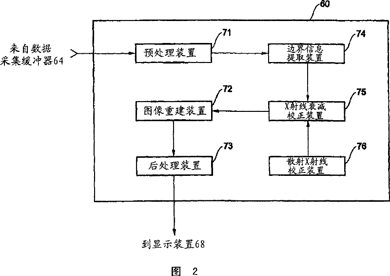
[0094] In the above-mentioned first preferred embodiment, a differential operation is performed on the projection information in the direction of the channel to extract boundary information of X-ray absorptivity changes. In this preferred embodiment, an embodiment will be described in which differential operation is performed on the projection information in the direction corresponding to the row direction of the X-ray detector to extract boundary information in the row direction, which is the row direction of the X-ray detector. The rotation direction is perpendicular to the width direction (hereinafter simply referred to as the row direction). In this embodiment, the boundary information extracting means 74 and the X-ray attenuation correcting means 75 will be described in more detail, and the description of other arrangements similar to the aforementioned preferred embodiments will be omitted.
[0095] In this embodiment, the boundary information extracting means 74 has a d...
no. 3 example
[0107] In order to extract the boundary information of X-ray absorptivity changes, in the above-mentioned first preferred embodiment, the differential operation is performed on the projection information in the channel direction, while in the above-mentioned second preferred embodiment, the present invention performs differential operation in the row direction . In this embodiment, an example will be described in which differential operations are performed on projection information in both the channel direction and the row direction to extract boundary information where X-ray absorptivity changes. In this preferred embodiment, the boundary information extraction means 74 and the X-ray attenuation correction means 75 will be described in more detail, and other arrangements similar to the first embodiment will not be described.
[0108]In this embodiment, the boundary information extracting means 74 has a difference means for performing differential operations on the projection ...
PUM
 Abstract
Description
Claims
Application Information
 - R&D
- Intellectual Property
- Life Sciences
- Materials
- Tech Scout
- Unparalleled Data Quality
- Higher Quality Content
- 60% Fewer Hallucinations
Browse by: Latest US Patents, China's latest patents, Technical Efficacy Thesaurus, Application Domain, Technology Topic, Popular Technical Reports.
© 2025 PatSnap. All rights reserved.Legal|Privacy policy|Modern Slavery Act Transparency Statement|Sitemap|About US| Contact US: help@patsnap.com


