Method and device for coating fluorescent powder on spiral fluorescent lamp tube

A technology of fluorescent tubes and phosphors, which is applied in the application of luminescent paints and the manufacture of tubes/lamp screens. It can solve the problems of uneven illumination brightness, waste of phosphor powder, and high additional costs, so as to ensure luminous brightness and uniformity, reduce Product production costs, effects of significant technological advancement

Inactive Publication Date: 2011-11-30
上海川石光电科技有限公司
View PDF0 Cites 0 Cited by
  • Summary
  • Abstract
  • Description
  • Claims
  • Application Information

AI Technical Summary

Problems solved by technology

The method of allowing the excess phosphor paste to flow out naturally under the action of gravity will inevitably lead to the following consequences: first, the formed phosphor layer is thick and uneven, and often results in local areas that are extremely thick or even piled up; second, Since the coating is thick and uneven, it will inevitably lead to low overall luminous efficiency and uneven illumination brightness, so it is difficult to guarantee the quality of new products; third, there is a serious waste of fluorescent powder, and it must be filled with a special 90 ° C heat Air, the additional cost is high; the fourth is that the overall production efficiency is low, it takes time to carry out the process of naturally flowing out the excess phosphor slurry, and it must be accompanied by the process of removing the phosphor layer accumulated at the nozzle.
Therefore, the cost of the product is relatively high, and the quality is difficult to guarantee. From the perspective of practicality and economy, the production process of the prior art coating spiral fluorescent tube phosphor layer is not ideal.

Method used


Image

  • Method and device for coating fluorescent powder on spiral fluorescent lamp tube
  • Method and device for coating fluorescent powder on spiral fluorescent lamp tube
  • Method and device for coating fluorescent powder on spiral fluorescent lamp tube

Examples


Embodiment Construction

[0035] The present invention will be further described below in conjunction with the accompanying drawings and typical embodiments.

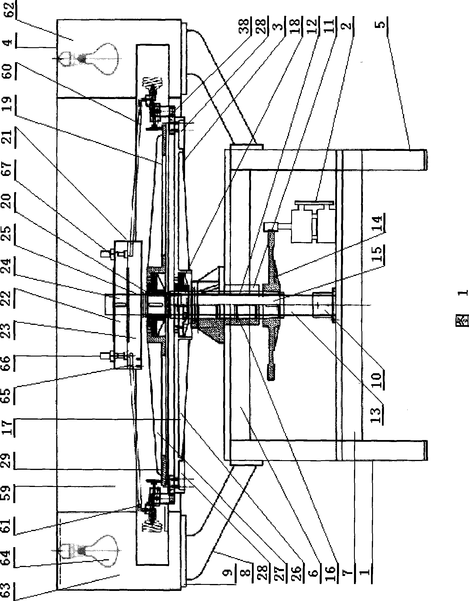
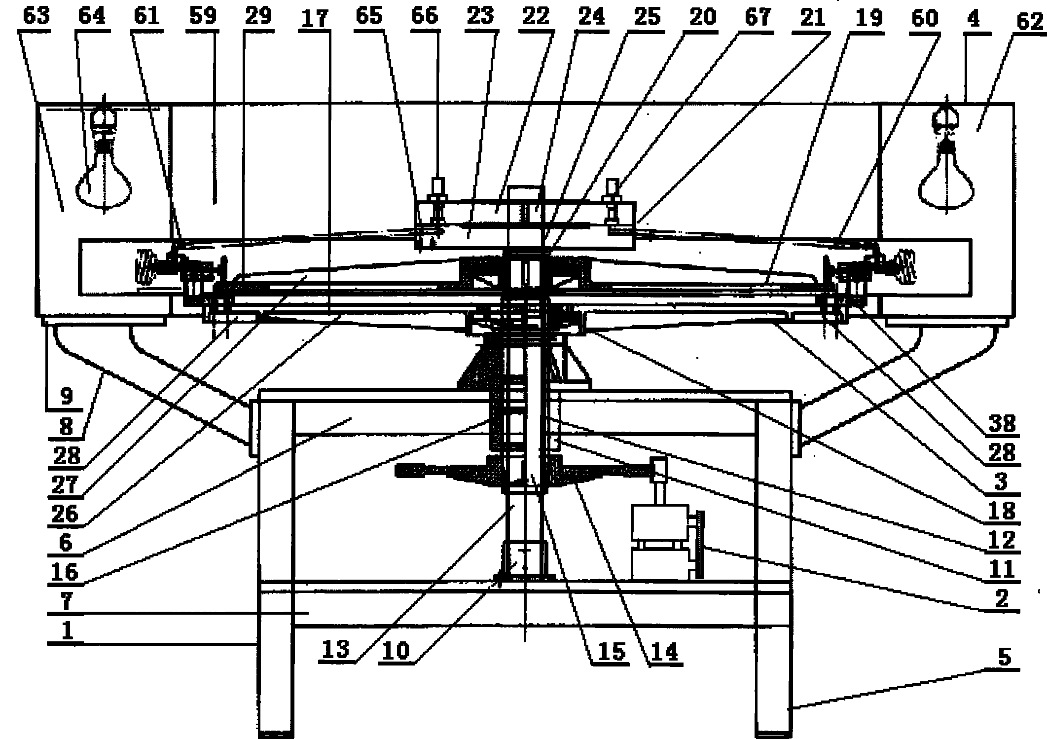
[0036] exist figure 1 and figure 2 Among them, the main body of the device for coating fluorescent powder on a spiral fluorescent tube of the present invention is mainly composed of a frame 1, a power drive mechanism 2, an action actuator 3 and a heating and drying system 4, wherein: the frame 1 is supported by support feet 5, up and down The seat frame 6 and 7 and the bracket 8 are formed, the main body of the bracket 8 is in the shape of an upwardly expanding conical ring, and its lower end is fixedly arranged on the outer side surface near the top edge of the supporting foot 5, and the upper top end is horizontal. A support plane 9 is provided, and the upper and lower support frames 6 and 7 are respectively horizontally arranged on the inner side surface of the middle and lower part of the support foot 5 and near the top end, and a spindle ...


PUM


Abstract

The invention relates to a method and device for coating fluorescent powder on a spiral fluorescent lamp tube, which adopts a functional device with rotation and revolution, uses normal temperature air as a hygroscopic agent, uses infrared radiation, oven baking and reciprocating air circulation for drying, The process of strengthening the coating makes the phosphor paste layer in the spiral curved glass tube evenly coated and solidified slowly, which can ensure that the thickness of the phosphor layer is uniform and not too thick, ensures the quality of the spiral fluorescent tube, and can save at least 10% Phosphor powder, increase the luminous efficiency by more than 3%. The device can be equipped with a considerable number of spirally curved glass tube mounting supports in the form of multiple heads and multiple stations at the same time. It rotates slowly, operates in sequence, and operates in cycles, which changes the traditional process of using special hot air at about 90 ° C to dehumidify. It has the positive technical effects of reducing production cost, improving work efficiency, reliable quality, convenient use and obvious energy-saving effect, and has strong practicability.

Description

technical field [0001] The invention relates to the technical field of fluorescent tube manufacturing technology, in particular to a method and a device for coating fluorescent powder on a spiral fluorescent tube. Background technique [0002] Among the high-power fluorescent tubes, the spiral fluorescent tube is favored by the market because of its energy saving, good lighting effect, compact structure, small size, high power and wide application range. In the manufacturing process of spiral fluorescent lamps, the process difficulty of evenly setting a phosphor layer on the inner wall of the spirally curved glass tube is the most difficult among all types of fluorescent lamps, and it is a major subject that manufacturers are currently studying to overcome. In the prior art, it is common to first pour phosphor slurry into the spirally curved glass tube, and then lower the end of the spirally curved glass tube to allow the excess phosphor slurry to flow out naturally under th...

Claims


Application Information

Patent Timeline
Patent Type & Authority Patents(China)
IPC IPC(8): H01J9/22
Inventor 叶昭钦
Owner 上海川石光电科技有限公司
Why Eureka
Try Eureka