Dynamic piezoelectric or electrostrictive ceramic drive power supply

A stretchable and piezoelectric technology, applied in the field of drive power circuits, can solve the problems of insufficient peak power of the drive, low frequency response of the drive, and high power dissipation

Inactive Publication Date: 2007-09-26
CHONGQING UNIV
View PDF0 Cites 11 Cited by
  • Summary
  • Abstract
  • Description
  • Claims
  • Application Information

AI Technical Summary

Problems solved by technology

However, the driving voltage range of the voltage is very large, and the power dissipation required by the circuit is very high. However, the design of the past piezoelectric ceramic driver focused more on static performance, and the peak cur...

Method used


Image

  • Dynamic piezoelectric or electrostrictive ceramic drive power supply
  • Dynamic piezoelectric or electrostrictive ceramic drive power supply
  • Dynamic piezoelectric or electrostrictive ceramic drive power supply

Examples


Embodiment 1

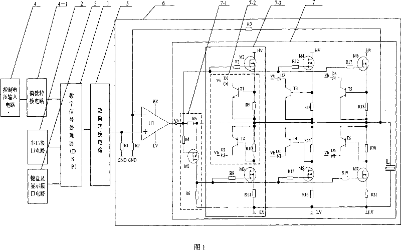
[0012] Embodiment 1: As shown in Figure 1: the piezoelectric ceramic driving power supply circuit includes a digital signal processor 1, an RS232 interface circuit 2, a keyboard and a display interface circuit 3, a control voltage input circuit 4, an analog-to-digital conversion circuit 4-1, a digital Analog conversion circuit 5, high voltage amplifying circuit 6. The specific connection method is as follows: the output terminal of computer and RS232 interface circuit 2 is connected to the input terminal of digital signal processor 1, the output terminal of keyboard and display interface circuit 3 is connected to the input terminal of digital signal processor 1, and the output of external analog input signal 4 is connected The terminal is connected to the input terminal of the analog-to-digital conversion circuit 4-1, the output terminal of the digital-to-analog conversion circuit 4-1 is connected to the input terminal of the digital signal processor 1, and the output terminal ...

Embodiment 2

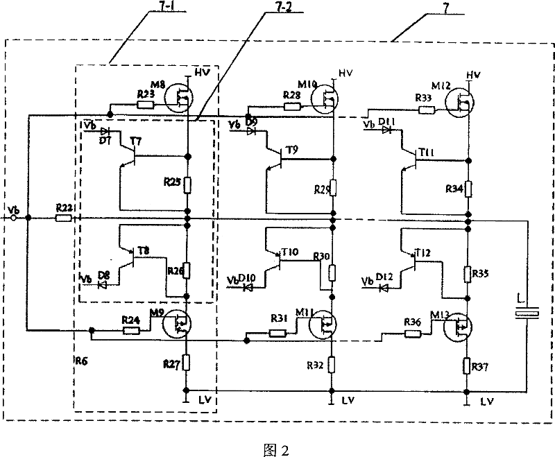
[0018] Embodiment 2: The difference between Example 2 and Example 1 is that the driving circuit is different. The driving circuit of Embodiment 2 is shown in FIG. , M9, R23, R25, R26, R27, R24, the specific connection relationship is that the gate of M8 is connected to one end of R23, the other end of R23 is connected to the output end of the high-voltage operational amplifier U1, the drain of M8 is connected to the high-voltage terminal HV, and M8 The source of R25 is connected to the common point of one end of resistor R25 and the base of T7, the other end of R25 is connected to one end of R26, and one end of R22 is connected at the same time, the other end of R26 is connected to the source of M9, and the gate of M9 is connected to one end of R24. The other end of R24 is connected to the output end of the high voltage operational amplifier U1, the drain of M3 is connected to one end of the resistor R27, and the other end of R27 is connected to the low voltage end LV. The oth...


PUM


Abstract

The invention relates to drive power source of piezoelectric ceramic that comprises RS232 interface circuit, digital signal processor (DSP), and keyboard and display interface circuit, high voltage regulated voltage circuit, high voltage amplification system and drive circuit. The output end of the RS232 interface circuit and keyboard and display interface circuit are connected with the input end of the digital signal processor, the input end of the analog-to-digital converter circuit controls the voltage signal, the output end is connected with the input end of the digital signal processor, the output end of the digital signal processor is connected with the input end of the analog-to-digital converter circuit, the output end of the analog-to-digital converter circuit is connected with the input end of the high voltage amplification system, the output end of the high voltage amplification system is connected with the positive pole of the piezoelectricity or electrostriction ceramics L, the negative pole is connected with the low voltage end LV. The invention adopts the digital signal processor as the core; the drive circuit adopts the multi groups of MOS tube to construct, the peak current and power is big, the circuit possesses property that the dynamic response is well, reliability is high, null shift is small, the precision is high, adjustment is convenient.

Description

technical field [0001] The invention relates to a driving power supply circuit of piezoelectric ceramics and electrostrictive ceramics, in particular to a dynamic driving technology of piezoelectric ceramics and electrostrictive ceramics. Background technique [0002] Piezoelectric ceramic micro-displacement device is a new type of micro-displacement device, which has been widely used in precision positioning, micro-electromechanical systems, nano-manufacturing technology, nano-bioengineering and other fields. The driving of piezoelectric ceramics is inseparable from the driving power supply of piezoelectric ceramics. Piezoelectric ceramics are equivalent to capacitive loads, and the displacement of a single piezoelectric ceramic is very small. Therefore, in practical applications, multiple piezoelectric ceramics are often used A certain way is combined to form a piezoelectric ceramic stack. In this way, the capacitance of piezoelectric ceramics will be larger, such as the ...

Claims


Application Information

Patent Timeline
IPC IPC(8): H02N2/00H02N2/06H02N2/14
Inventor 王代华丁文明
Owner CHONGQING UNIV
Why Eureka
Try Eureka