System and method for detecting optical fiber wiring troubles

A detection system and optical fiber line technology, applied in the field of communication, can solve the problems of the detection system and method for optical fiber line faults, such as construction difficulties, and achieve the effect of reducing the difficulty and simplifying the test method.

Inactive Publication Date: 2007-09-26
HUAWEI TECH CO LTD
View PDF0 Cites 54 Cited by
  • Summary
  • Abstract
  • Description
  • Claims
  • Application Information

AI Technical Summary

Problems solved by technology

[0011] In order to solve the defect of difficult construction of the optical fiber line fault detection system and method in the prior art, the present invention provides a simple construction optical fiber line fault detection system and method

Method used


Image

  • System and method for detecting optical fiber wiring troubles
  • System and method for detecting optical fiber wiring troubles
  • System and method for detecting optical fiber wiring troubles

Examples


Embodiment Construction

[0032] The present invention will be further described below in conjunction with the accompanying drawings and typical implementations, but it is not intended to limit the present invention.

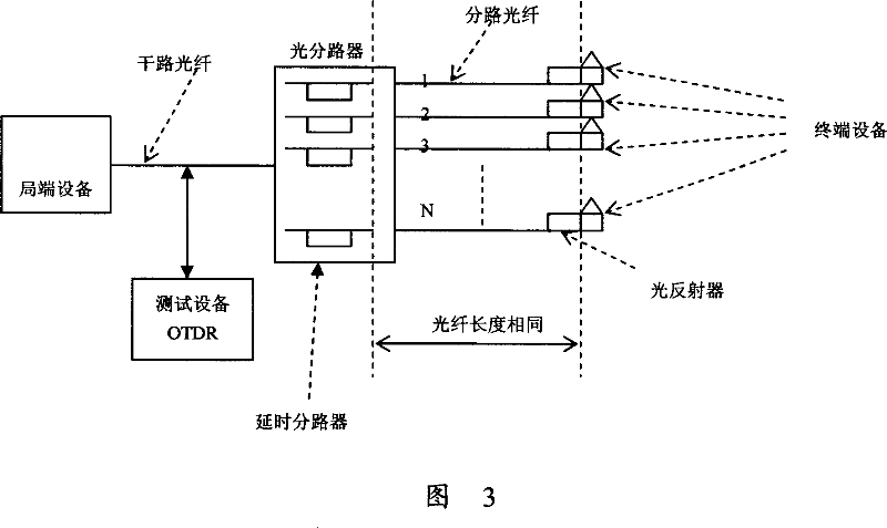
[0033] In the technical solution of the present invention, it is required that the branch optical fibers, that is, the optical fibers connecting the optical splitter to the user terminal equipment, have the same length. An optical reflector is arranged on the branch optical fiber near the terminal between the optical splitter and each terminal to reflect the test wavelength, for example, the test wavelength is 1650nm. The optical splitter Splitter has the function of generating different delay times for the optical signals branched from different ports, which can be realized by optical delay or optical winding. The test equipment OTDR is used to test the trunk fiber access between the central office equipment and the optical splitter.

[0034] The implementation process of the optical f...


PUM


Abstract

The invention relates to fields of communication, specially a detecting system and method of optical fiber line fault. The detecting system includes: local equipment, terminal equipment, at least one light delay branching units which are between the local equipment and terminal equipment, test wavelength reflect device which is connected between the light delay branching units and terminal equipment and close to the spur track fiber of the terminal equipment, and test device OTDR of main circuit fiber which is between the light delay branching units and local equipment, said light delay branching units generate different delay time for light signal of different port branching light path, thereinto the length of branching fiber of said light delay branching units and terminal equipment is the same. The detecting method and system of the fiber line fault in this invention can simplify the test method of fiber line fault diagnosis, and decrease the cost of fiber construction.

Description

technical field [0001] The invention relates to the field of communications, in particular to a method and system for detecting faults in optical fiber lines. Background technique [0002] As shown in FIG. 1 , a typical point-to-multipoint optical network with optical fiber access usually includes an office equipment OLT, multiple passive optical splitters Splitter, multiple remote equipment ONTs and multiple optical fibers. The central office equipment and the optical splitter are connected through an optical fiber to form a main optical fiber. The optical splitter is respectively connected to multiple remote devices through multiple branch optical fibers. [0003] The existing methods for detecting faults of optical fiber lines are basically implemented by using OTDR (Optical Time Domain Reflect meter, OTDR) technology. That is, the OTDR is used to transmit an optical pulse into the optical fiber line, and the fault diagnosis of the optical fiber line is carried out by m...

Claims


Application Information

Patent Timeline
Patent Type & Authority Applications(China)
IPC IPC(8): H04B10/152H04B10/213H04B10/071H04B10/079
Inventor 黄伟赵峻谭培龙江涛
Owner HUAWEI TECH CO LTD
Why Eureka
Try Eureka