Diffuseur of liquid pump

A technology of a dispenser and a liquid pump, which is applied in the directions of liquid distribution, liquid injection devices, household containers, etc., can solve the problems of poor discharge function of the liquid pump dispenser, deterioration of the discharge function of the liquid pump dispenser, and increase of the amount of liquid.

Inactive Publication Date: 2007-10-03
TAESUNG IND
View PDF0 Cites 16 Cited by
  • Summary
  • Abstract
  • Description
  • Claims
  • Application Information

AI Technical Summary

Problems solved by technology

[0021] However, in the conventional liquid pump dispenser, a problem arises in that since the pumping passage 132b leads to or is exposed to the outside, it is in a state where the discharge of the liquid to the outside is interrupted, so an air passage is formed outside and the pump Send between channel 132b
Also, since moisture evaporates through the air passage, the liquid present in the nozzle 150, the discharge guide passage 141b, the discharge connection holes 141a and 142, and the pumping passage 132b may solidify, causing the discharge function of the liquid pump dispenser to deteriorate.
Specifically, in the case where the liquid present in the nozzle 150 or the front end of the discharge guide passage 141b is solidified, the discharge function of the liquid pump dispenser is significantly deteriorated.
[0023] In addition, there is a disadvantage in that when the discharge of the liquid is interrupted, the amount of liquid held in the nozzle 150 and the discharge guide passage 141b increases because the liquid filling the nozzle 150 and the discharge guide passage 141b remains as it is.

Method used


Image

  • Diffuseur of liquid pump
  • Diffuseur of liquid pump
  • Diffuseur of liquid pump

Examples


Embodiment Construction

[0036] Reference will now be made in detail to an embodiment of the invention, an example of which is illustrated in the accompanying drawings.

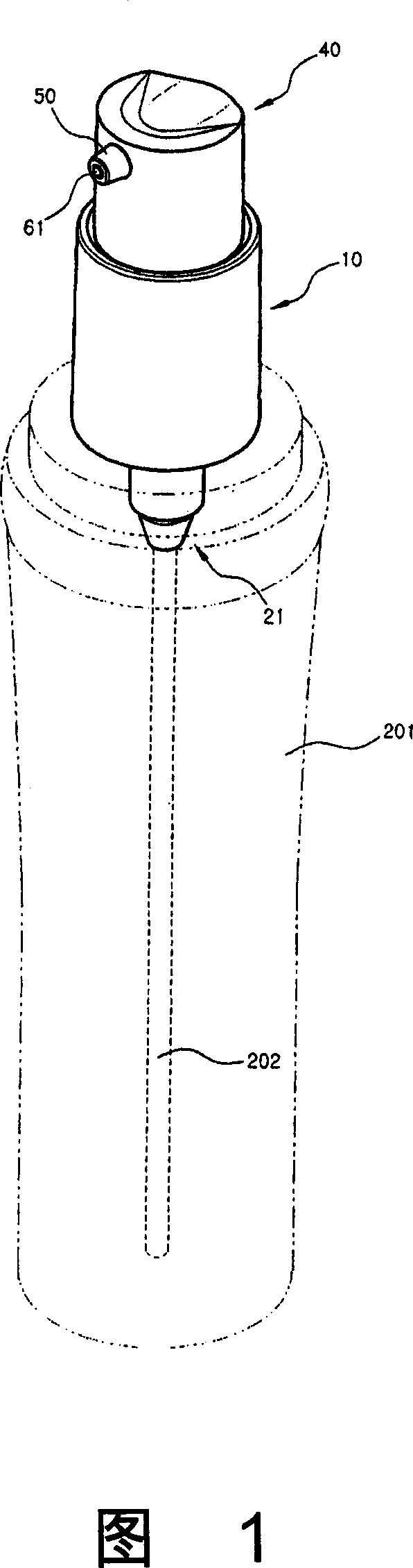
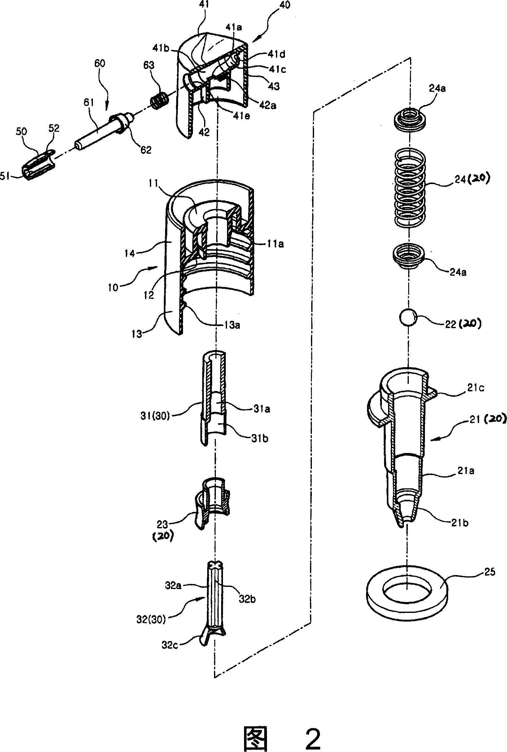
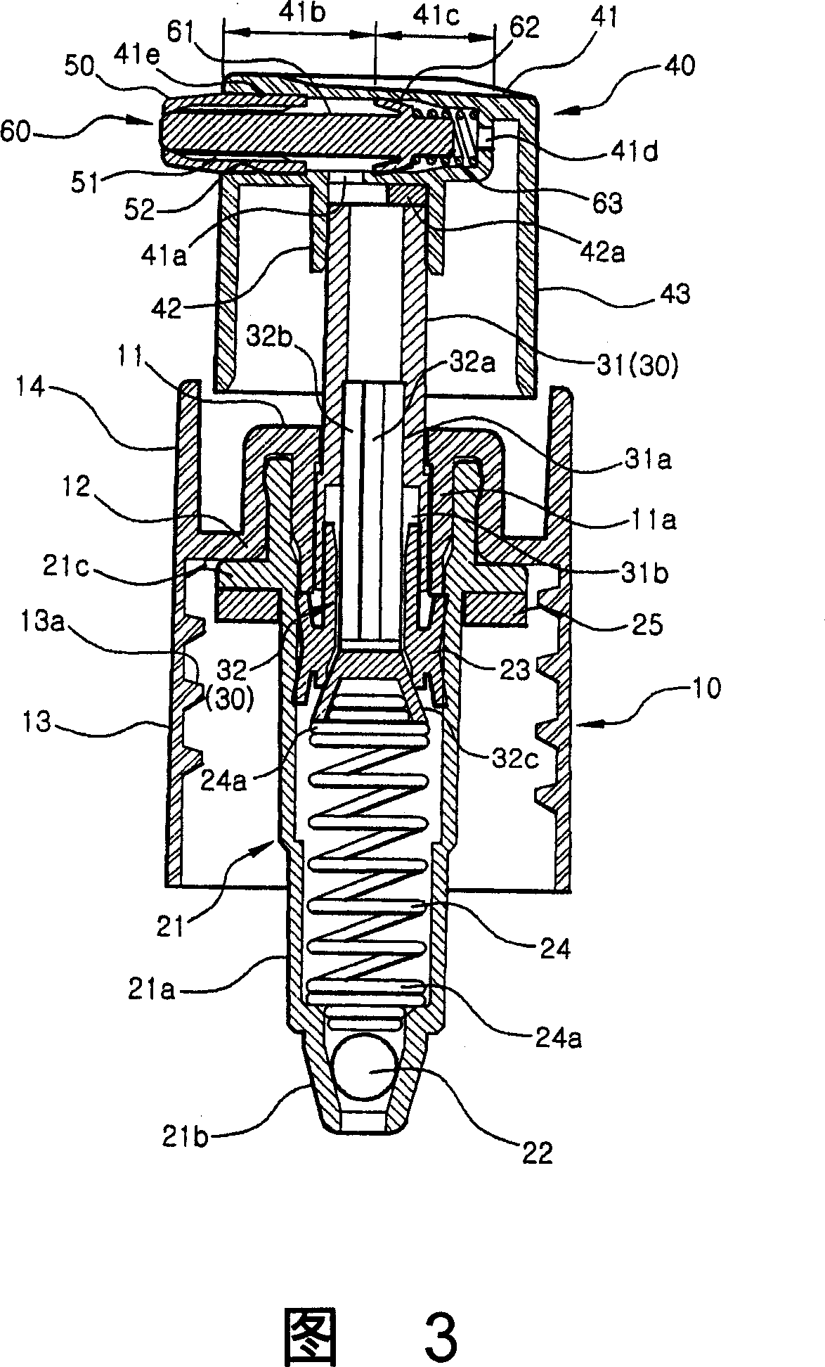
[0037] 1 is a perspective view showing the assembly of a liquid pump dispenser according to an embodiment of the present invention, FIG. 2 is an exploded perspective view showing a liquid pump dispenser according to an embodiment of the present invention, and FIG. An assembled sectional view of the liquid pump dispenser according to an embodiment of the present invention, FIG. 4 is a bottom view of the button shown in FIG. 3 , and FIG. 5 is a sectional view of the nozzle shown in FIG. 3 .

[0038] Referring to the accompanying drawings, the liquid pump dispenser according to the embodiment of the present invention comprises: a cap 10 coupled with the upper end of a liquid container 201; a pump operation part 20; a button 40 coupled to the upper end of the piston 30; a nozzle 50 installed through the front of the button 40;

[0039] ...


PUM


Abstract

Disclosed is A liquid pump dispenser. A fluid path opening and closing section has a rod-shaped body part which is installed in a discharge guide path and a sliding guide groove of a push button, a wing part which is formed around the body part to be brought into close contact with an inner surface of the sliding guide groove, and a return spring which is disposed in the sliding guide groove to bias the wing part toward the discharge guide path. The body part is retracted to an opening position for opening the discharge guide path with respect to the outside by pressure applied from pumped liquid entering the discharge guide path to the wing part and is extended to a closing position for closing the discharge guide path with respect to the outside by pressure applied from the return spring to the wing part.

Description

technical field [0001] The present invention relates to a liquid pump dispenser, and more particularly, to a liquid pump dispenser for discharging liquid, such as cosmetics, from a liquid container by pumping. Background technique [0002] A conventional liquid pump dispenser known and used in the art is coupled to the upper end of a liquid container for pumping liquid such as cosmetics out of the liquid container. As used herein, the term "liquid" includes substances, such as creams, which have a viscosity sufficient to allow the substance to be pumped. [0003] Fig. 8 is an assembled sectional view showing a conventional liquid pump dispenser. [0004] Referring to FIG. 8 , the conventional liquid pump dispenser includes a cap 110 coupled to the upper end of the liquid container 201 (see FIG. 1 ), a pumping operation with a tubular cylinder 121 coupled to the cap 110 and piston 130. part 120 , a button 140 coupled to the upper end of the piston 130 and a nozzle 150 mount...

Claims


Application Information

Patent Timeline
Patent Type & Authority Applications(China)
IPC IPC(8): B05B9/04B65D83/16
CPCA45D34/02B05B11/3023B05B11/3016B05B11/0067B05B11/1016B05B11/1023
Inventor 裴海童
Owner TAESUNG IND
Why Eureka
Try Eureka