Color filter and manufacturing method thereof

a manufacturing method and color filter technology, applied in the field of color filter manufacturing method, can solve the problems of complex manufacturing of color filter, low efficiency, and difficulty in displaying, and achieve the effect of improving production efficiency and simplifying the manufacturing process

Inactive Publication Date: 2013-01-24
SHENZHEN CHINA STAR OPTOELECTRONICS TECH CO LTD
View PDF5 Cites 12 Cited by
  • Summary
  • Abstract
  • Description
  • Claims
  • Application Information

AI Technical Summary

Benefits of technology

[0006]The primary objective of the present invention is to provide a color filter and a manufacturing met

Problems solved by technology

However, the spacer layer is of a uniform height and the surface of a thin film transistor (TFT) layer to which the color filter is attached usually has a nonuniform height, both the rotating time and the recovery time of liquid crystals are different in the attachment area of varying h

Method used


Image

  • Color filter and manufacturing method thereof
  • Color filter and manufacturing method thereof
  • Color filter and manufacturing method thereof

Examples


first embodiment

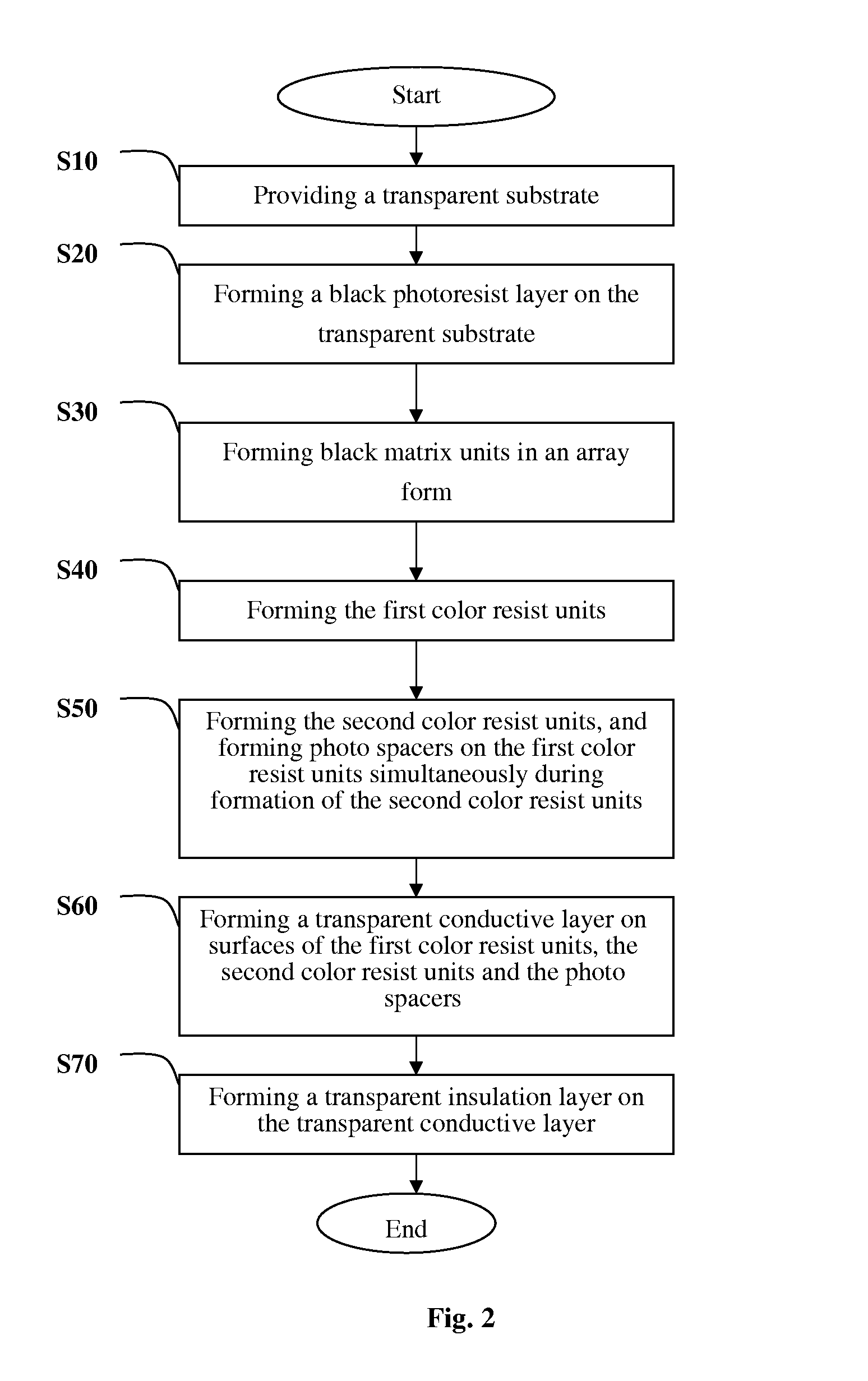
[0077]In order to elucidate the manufacturing method of a color filter of the present invention more clearly, the solution of the present invention will be further detailed with reference to FIG. 2. Referring to FIG. 2, there is shown a flowchart illustrating the manufacturing method of a color filter according to the present invention. The manufacturing method of a color filter comprises the following steps of:

[0078]step S10: providing a transparent substrate;

[0079]step S20: forming a black photoresist layer on the transparent substrate, and specifically, forming a black photoresist layer on the transparent substrate through coating;

[0080]step S30: forming black matrix units in an array form. After the black photoresist layer is formed, the black matrix units in an array form can be obtained through a vacuum drying process, a process for removing the photoresist material at the edges, a pre-baking and cooling process, a exposure process that uses a photomask, a developing process, ...

second embodiment

[0094]For color filters of the three primary colors (i.e., the red color, the green color and the blue color) currently available, the present invention further provides a manufacturing method of a color filter. Referring to FIG. 4, there is shown a flowchart illustrating the manufacturing method of a color filter.

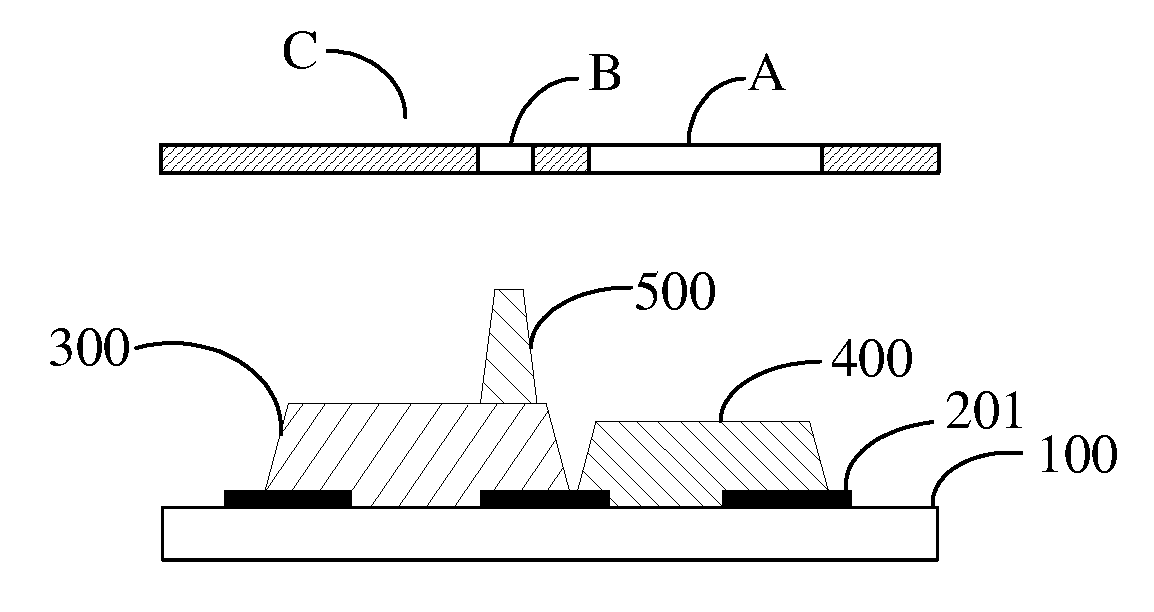
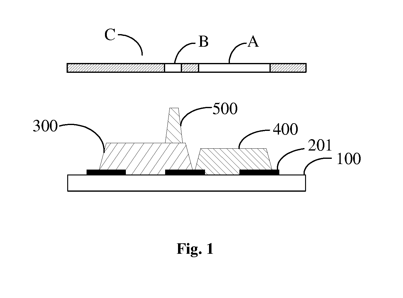
[0095]In this embodiment, the color filter comprises first color resist units, second color resist units and third color resist units, which are actually red color resist units, green color resist units and blue color resist units. A color pixel unit is formed by one first color resist units, one second color resist units and one third color resist units. As shown in FIG. 4, the manufacturing method of a color filter comprises the following steps of:

[0096]step S11: providing a transparent substrate;

[0097]step S12: forming a black photoresist layer on the transparent substrate;

[0098]step S13: forming black matrix units in an array form;

[0099]step S14: forming the first colo...

third embodiment

[0117]Specifically, referring to FIG. 6, there is shown a flowchart illustrating the manufacturing method of a color filter according to the present invention. The manufacturing method of a color filter comprises the following steps of:

[0118]step S110: providing a transparent substrate;

[0119]step S120: forming a black photoresist layer on the transparent substrate;

[0120]step S130: forming black matrix units in an array form;

[0121]step S140: forming the first color resist units;

[0122]step S150: forming the second color resist units, and forming first photo spacers on the first color resist units simultaneously during formation of the second color resist units;

[0123]step S160: forming the third color resist units, and forming second photo spacers on the second color resist units simultaneously during formation of the third color resist units;

[0124]step S170: forming a transparent conductive layer on surfaces of the first color resist units, the second color resist units, the third col...


PUM


Abstract

The present invention provides a color filter and a manufacturing method of the color filter. The color filter comprises first color resist units and second color resist units, and a pixel layer is formed by the first color resist units and the second color resist units. The manufacturing method comprises the following step of: after the first color resist units are formed, forming photo spacers for controlling a gap between an array substrate and a color filter substrate simultaneously when the second color resist units are formed. The present invention can reduce the number of manufacturing processes and effectively reduce the manufacturing cost of liquid crystal displays (LCDs).

Description

BACKGROUND OF THE INVENTION[0001]1. Technical Field[0002]The present invention relates to a manufacturing method of a color filter, and more particularly, to a color filter provided with photo spacers in a liquid crystal display (LCD) and a manufacturing method of the color filter.[0003]2. Description of Related Art[0004]In the conventional process for manufacturing a color filter, spacers are generally disposed in such a way that a spacer layer of a uniform height is disposed in a selected color photoresist area of a color resist unit region to form a spacer for liquid crystal filling. However, the spacer layer is of a uniform height and the surface of a thin film transistor (TFT) layer to which the color filter is attached usually has a nonuniform height, both the rotating time and the recovery time of liquid crystals are different in the attachment area of varying heights when the color filter is attached to the TFT layer, thereby incurring problems in displaying.[0005]In view of...

Claims


Application Information

Patent Timeline
IPC IPC(8): G02B5/22B05D5/12G03F7/20B05D5/06
CPCG02B5/22G03F7/0007G02B5/201
Inventor WU, CHUN-MING
Owner SHENZHEN CHINA STAR OPTOELECTRONICS TECH CO LTD
Why Eureka
Try Eureka