Treating device for sludge self-return aerobic bios

A technology of aerobic biology and treatment equipment, which is applied in the direction of aerobic process treatment, sustainable biological treatment, biological water/sewage treatment, etc., and can solve the problems of sludge not returning in time, sludge floating phenomenon, sludge accumulation, etc. Achieve the effect of saving sludge return equipment and power costs, preventing sludge swelling, and reducing sludge flow rate

Inactive Publication Date: 2007-10-03
ZHEJIANG UNIV
View PDF1 Cites 32 Cited by
  • Summary
  • Abstract
  • Description
  • Claims
  • Application Information

AI Technical Summary

Problems solved by technology

The aerobic area of ​​this technical scheme is directly connected to the sedimentation area, that is, the effluent and the sludge return flow are in the same area. When the amount of treated water is large, that is, when

Method used


Image

  • Treating device for sludge self-return aerobic bios

Examples


Embodiment Construction

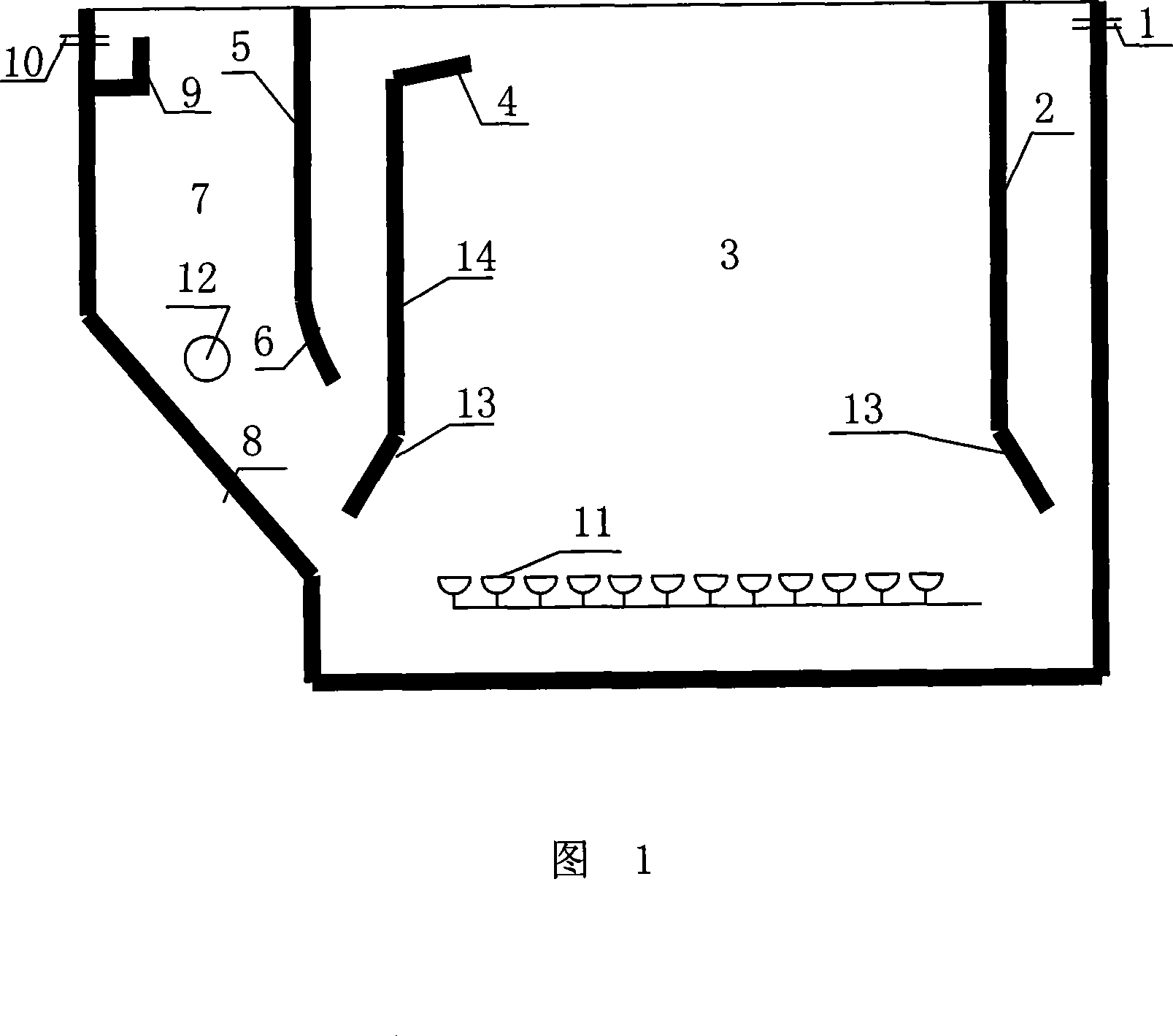
[0016] As shown in Figure 1, a sludge self-reflux aerobic biological treatment device includes a tank body 14, the two ends of the tank body 14 are respectively provided with a water inlet 1 and a water outlet 10, and the tank body 14 is provided with a The diversion area 15, the aeration area 3 and the sludge sedimentation area 7 are separated by the plate 2 and the partition 14 but communicated at the bottom. The diversion swash plate 13 with an angle of 135 degrees, the ratio of the length of the sludge diversion buffer slant plate 4 to the width of the diversion area 15 is 1:0.8-1.2, which forms an angle of 15-30 degrees with the horizontal plane.

[0017] The lower end of the water inlet deflector 2 is provided with a deflector inclined plate 13 that forms an angle of 45-60 degrees with the horizontal plane.

[0018] An aeration device 11 is provided at the bottom of the aeration zone 3 .

[0019] The bottom of the sludge settling area 7 is provided with an inwardly incl...


PUM


Abstract

An aerobic biologic processing apparatus with automatic reflux of sludge by integrating different water flow forms in it has a pool body with water inlet and outlet at its both ends. Said pool body is divided into a flow guiding area with guide plate and partition, an aerating area with aerator on its bottom, and a sludge depositing area with inward inclined plate, baffle plate and overflow dam.

Description

technical field [0001] The invention relates to a sewage treatment device, in particular to a sludge self-reflux aerobic biological treatment device. Background technique [0002] At present, for small-scale sewage treatment facilities, due to the small amount of sewage water, if the traditional aerobic process is adopted, several necessary treatment structures such as aeration tanks, sedimentation tanks, and sludge concentration tanks must be installed. Power equipment such as backflow pumps have high investment costs per ton of water, and are prone to sludge bulking, so they are not suitable for small-scale sewage treatment facilities. [0003] Invention patent application 200610036025.2 discloses an integrated self-reflux multi-stage biochemical sewage treatment device. The device includes an anaerobic zone, a sewage inlet is set at the lower part of the anaerobic zone, and an anoxic zone is set between it and the anaerobic zone. The partition wall, the aerobic zone, the...

Claims


Application Information

Patent Timeline
IPC IPC(8): C02F3/12C02F3/02
CPCY02W10/10
Inventor 冯华军沈东升郑元格
Owner ZHEJIANG UNIV
Why Eureka
Try Eureka