
Light emitting module with automatically regulated light emitting power and its power regulating method

An automatic adjustment and light-emitting module technology, which is applied in the direction of electroluminescence light source, semiconductor device of light-emitting element, light source, etc., can solve the problems of increasing the volume of light-emitting diodes, reducing the service life, and overheating of light-emitting diodes

Inactive Publication Date: 2007-10-03
陈建中
View PDF0 Cites 12 Cited by
  • Summary
  • Abstract
  • Description
  • Claims
  • Application Information

AI Technical Summary

Problems solved by technology

However, LEDs have their temperature-limited ratings in the operating mode. If they are used at high temperatures for a long time with insufficient heat dissipation, the aging of the LEDs will be accelerated, the luminous efficacy will be reduced, and the lifespan will be greatly shortened. Therefore, how to use Affecting the high temperature derivation of light-emitting diodes is a problem worth exploring
[0004] In the known technology, in order to achieve the effect of heat dissipation, most of the light-emitting modules that use light-emitting diodes as light sources are designed to increase the heat dissipation medium (such as heat dissipation fins of various materials, etc.) by predicting the total heat dissipation needs in advance. The design often increases the size of the entire light-emitting diode, which cannot achieve the best luminous efficiency under the requirements of small size and good heat dissipation
In addition, the heat dissipation through the heat dissipation medium is in a relatively passive state, and the heat can only be exported according to the heat dissipation degree of the heat dissipation medium itself, but cannot be actively judged to adjust the temperature, so the LED still has the risk of overheating

Method used


Image

  • Light emitting module with automatically regulated light emitting power and its power regulating method
  • Light emitting module with automatically regulated light emitting power and its power regulating method
  • Light emitting module with automatically regulated light emitting power and its power regulating method

Examples


Embodiment Construction

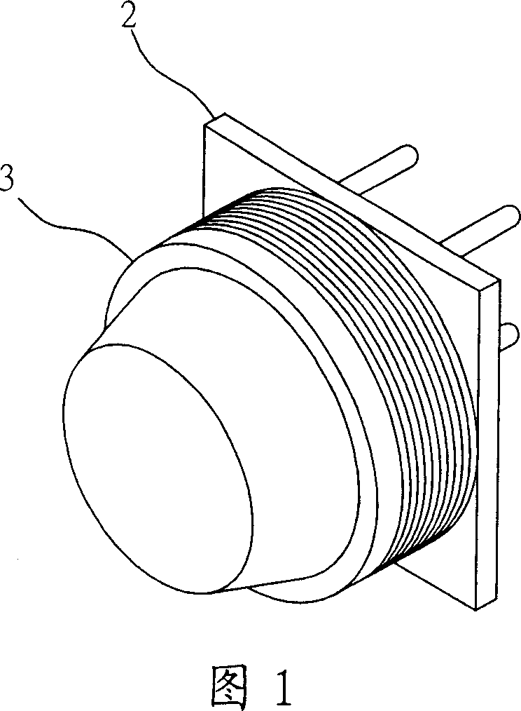
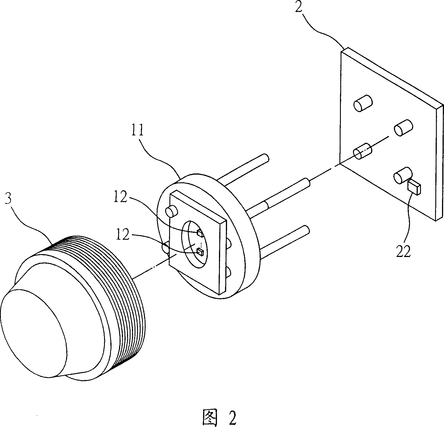
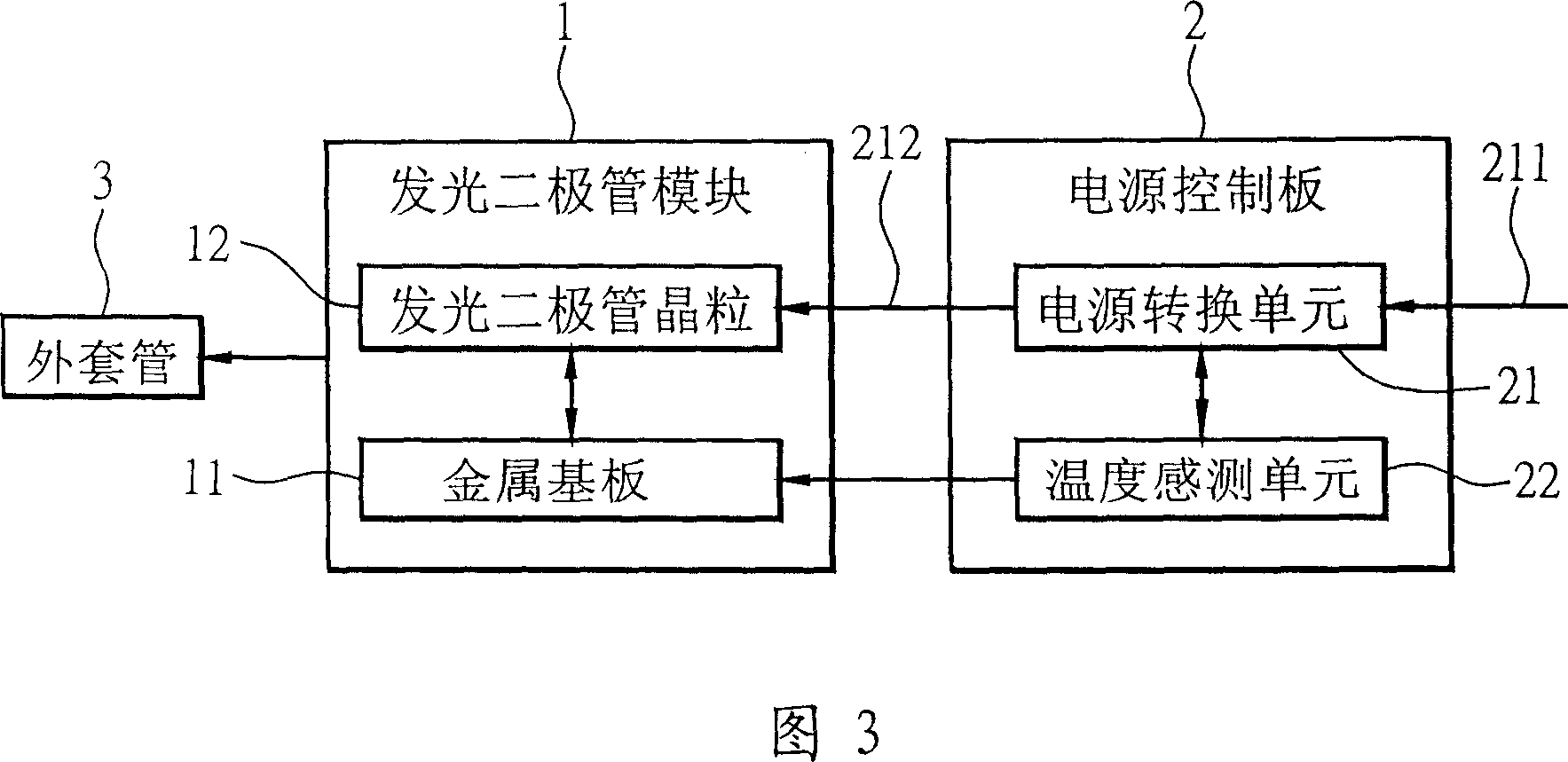
[0032] Please refer to Figure 1 and Figure 2, which are schematic diagrams and three-dimensional exploded views of the light-emitting module that automatically adjusts the light-emitting power of the present invention. The LED module 1 is covered by the outer sleeve 3 and then electrically connected with the power control board 2 . In the light emitting diode module 1, at least one light emitting diode crystal grain 12 is included on the metal substrate 11; and a temperature sensing unit 22 is included on the power control board 2 to connect the power control board 2 and the light emitting diode. When the diode module 1 is combined, the temperature of the environment where the light-emitting diode die 12 is detected by physically leaning against the metal substrate 11, and different temperature measurement values ​​are generated at any time to automatically adjust the luminous power of the light-emitting module .

[0033] Please refer to FIG. 3 , which is a block diagram of a...


PUM


Abstract

The present invention is one kind of light emitting module with automatically regulated light emitting power and its power regulating method. The light emitting module includes one LED module and one power source controlling board connected electrically to the LED module. The power source controlling board has and one thermal sensing unit for measuring environment temperature and one power source adaptor unit to convert the first power source into the second power source based on the measured temperature value. The light emitting power is regulated automatically, that is, the light emitting power is lowered to lower the temperature in condition of higher environment temperature and raised to raise brightness in condition of lower environment temperature.

Description

technical field [0001] The invention relates to a light emitting module, in particular to a light emitting module which automatically adjusts the light emitting power and a method for automatically adjusting the light emitting power. Background technique [0002] Light-emitting diodes have been paid more and more attention in recent years, especially for high-brightness light-emitting diodes (HB LEDs), the demand has been greatly increased, and a frenzy has been set off in the industry. Compared with traditional incandescent light bulbs, high-brightness light-emitting diodes have the advantages of power saving, long service life, high durability and fast response. At present, the popular applications of high-brightness light-emitting diodes are not only in general lighting, commodity lighting, automotive lighting, outdoor billboards and traffic information display, but also due to the progress and development of consumer electronics products, it has become more popular in va...

Claims


Application Information

Patent Timeline
IPC IPC(8): F21V29/00F21V23/00H05B33/08F21Y101/02F21Y115/10H05B44/00
Inventor 陈建中
Owner 陈建中
Learn More