Fuel cell system and method

A fuel cell system, fuel cell technology, applied in the direction of fuel cells, fuel cell additives, transportation fuel cell technology, etc., can solve the problem of catalyst activity reduction

Inactive Publication Date: 2007-10-03
TOYOTA JIDOSHA KK +1
View PDF1 Cites 13 Cited by
  • Summary
  • Abstract
  • Description
  • Claims
  • Application Information

AI Technical Summary

Problems solved by technology

One of the main reasons is that due to the long-term operation of the fuel cell, impurities (such as S content, CO, etc.) are attached to t

Method used


Image

  • Fuel cell system and method

Examples


Embodiment Construction

[0050] Hereinafter, preferred embodiments of the present invention will be described with reference to the accompanying drawings.

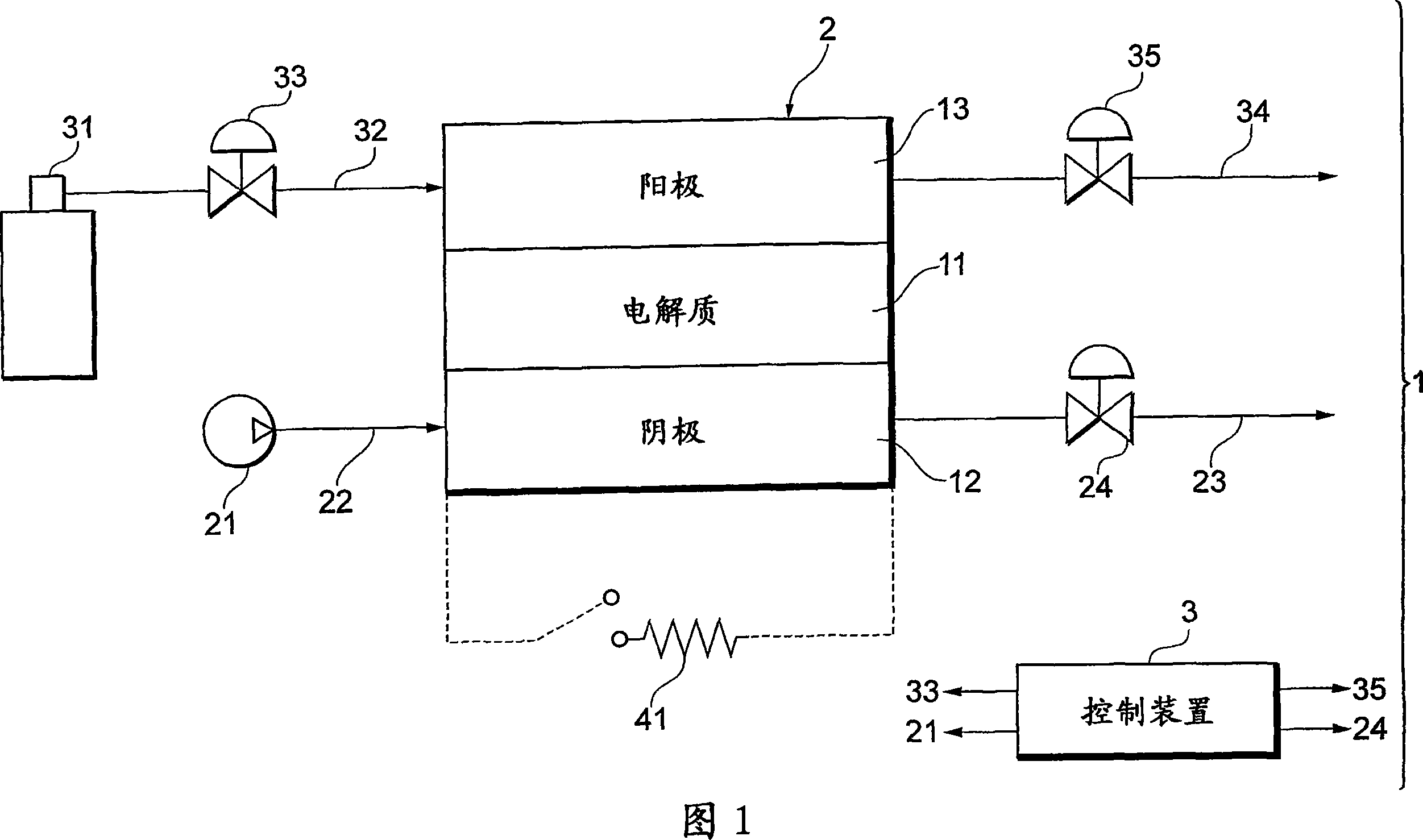
[0051] As shown in FIG. 1 , for example, a fuel cell system 1 mounted on a fuel cell vehicle includes a solid polymer electrolyte type fuel cell 2 suitable for vehicle use and a control device 3 that controls the entire system in an integrated manner. The fuel cell 2 has a stack structure in which a plurality of single-cell cells are stacked, receives supply of oxygen (air) as an oxidizing gas and hydrogen as a fuel gas, and generates electric power. In addition, when the fuel cell 2 is a stationary type, it is preferably a solid polymer electrolyte type or a phosphoric acid type. Even a stationary fuel cell system has the same fuel cell 2 and the same control device 3 .

[0052] A single cell of the fuel cell 2 is configured by arranging a cathode 12 (air electrode) and an anode 13 (fuel electrode) on both sides of an electrolyte membrane 11 com...


PUM


Abstract

There is provided a fuel cell system capable of appropriately regenerating catalyst at the cathode side or the anode side. The fuel cell system (1) includes regeneration means (21, 24, 33, 35) for controlling the gas supply amount of a fuel gas and a oxidant gas supplied to a fuel cell (2) so as to recover the lowering of activity of the catalyst of the fuel cell (2). The catalyst regeneration process at the side of the cathode (12) of the fuel cell (2) is performed by regeneration means which reduces the flow rate of the oxidant gas to less than a stationary request in the relationship with the fuel gas, thereby lowering the cell voltage of the fuel cell (2) to a predetermined voltage. The catalyst regeneration process at the side of the anode (13) is also performed by the regeneration means which reduces the flow rate of the fuel gas to less than a stationary request in the relationship with the oxidant gas.

Description

technical field [0001] The present invention relates to a fuel cell system for regenerating a catalyst on the cathode side or the anode side of a fuel cell and to a method therefor. Background technique [0002] For solid polymer fuel cells, the output voltage will decrease after a period of time under a certain output current. One of the main reasons is that due to the long-term operation of the fuel cell, impurities (such as S content, CO, etc.) are attached to the catalyst (such as Pt) on the cathode side or the anode side of the fuel cell, resulting in a decrease in the activity of these catalysts. . [0003] As a fuel cell system that solves this problem, a fuel cell system in which a load is provided in parallel with a fuel cell is known (for example, refer to Patent Document 1). In this case, the catalyst on the cathode side is regenerated by excessively supplying both the oxidant gas and the fuel gas to the fuel cell and passing a current larger than the rated oper...

Claims


Application Information

Patent Timeline
IPC IPC(8): H01M8/04H01M8/10
CPCY02T90/34B60L11/1885B60L11/1898Y02T10/7022H01M8/1002H01M8/04238B60L11/1887B60L1/02Y02E60/521B60L11/005H01M8/1007B60L50/40B60L50/72B60L58/31B60L58/40Y02T10/70Y02T90/40Y02E60/50
Inventor 曾一新
Owner TOYOTA JIDOSHA KK
Why Eureka
Try Eureka