Detecting mechanism for needle lifting position of electronic jacquard machine
An electronic jacquard and detection mechanism technology, which is applied in the field of textile machinery, can solve the problems of high cost, low reliability, and high detection cost, and achieve the effects of high installation density, reliable action, and simple structure
- Summary
- Abstract
- Description
- Claims
- Application Information
AI Technical Summary
Problems solved by technology
Method used
Image
Examples
Embodiment 1
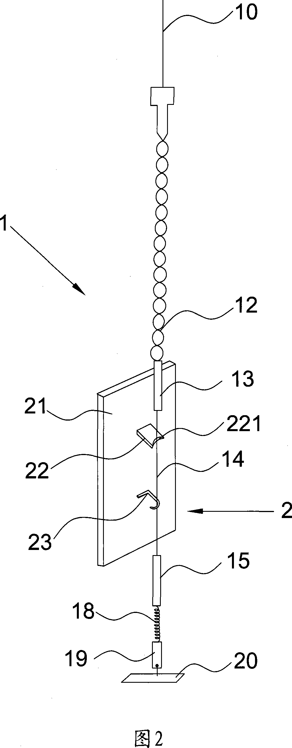
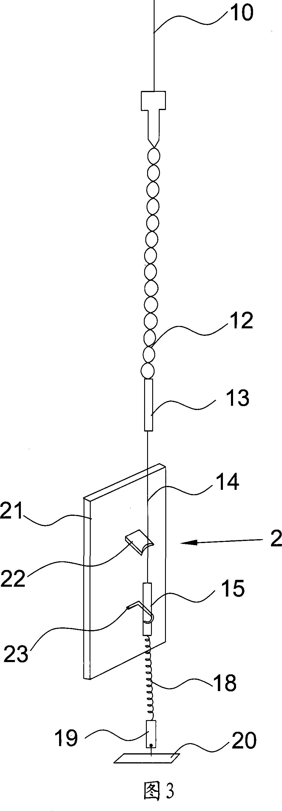
[0031] As shown in accompanying drawings 1 and 2, the electronic jacquard machine needle position detection mechanism includes a lifting needle 10 and a connecting part 1 connected to the lower end of the lifting needle 10, and the connecting part 1 includes a wire 12 connected in sequence , upper nylon joint 13, steel heald 14, lower nylon joint 15, elastic member 18, pendant 19, fixed frame 20, wherein said through-wire 12, upper nylon joint 13, lower nylon joint 15 are the insulating parts of connecting parts 1 , the steel heald 14 is the conductor part of the connecting part 1, and when the lifting needle 10 is jacquard and thus moves up and down, it will drive the connecting part 1 to move up and down accordingly.
[0032] Accompanying drawing 1 and accompanying drawing 2 also comprise the detection switch 2 that is used for detecting the position of raising needle, and this detection switch 2 comprises insulating board 21, the first electrode 22 that is fixedly arranged o...
Embodiment 2
[0040] Accompanying drawing 4 and accompanying drawing 5 are the schematic diagrams that the detection switch in this embodiment is in two states of conduction and disconnection. This embodiment is basically the same as Embodiment 1, and steel heddle 14 and nylon joint are still used as the detection switch 2. The difference between the movable electrodes is that in this embodiment, the first electrode 22 of the detection switch 2 is formed by a baffle with a hole 222 in the middle, and the second electrode 23 is formed by a baffle with a U-shaped groove 231 at the upper end. Moreover, the distance between the bottom of the U-shaped groove 231 and the insulating plate 21 is greater than the distance between the center of the hole 222 of the first electrode 22 and the insulating plate 21 . During installation, the movable electrode passes through the outer wall of the U-shaped groove of the second electrode 23 and goes upwards over the inner wall of the hole 222 of the first ele...
Embodiment 3
[0043] As shown in accompanying drawing 6 and accompanying drawing 7, the difference between this embodiment and embodiment one is: in this embodiment, the movable electrode adopts the insulated through-wire 12 that is connected with lifting pin 10, and through-wire 12 is specially made Thin rope has good wear resistance, no elongation, no static electricity, small surface friction coefficient, and good softness. The through wire is an insulating material. In order to make the conductor part required by the active electrode, a section of conductive layer is partially processed on the surface of the through wire 12, so that the part of the conductive layer on the through wire and the unprocessed through wire form the conductor of the active electrode. Department and insulation department.
[0044] At the same time, in combination with the good flexibility of the through wire, in order to keep it in contact with the first electrode 22 and the second electrode 23, in the present ...
PUM
 Abstract
Description
Claims
Application Information
 - R&D
- Intellectual Property
- Life Sciences
- Materials
- Tech Scout
- Unparalleled Data Quality
- Higher Quality Content
- 60% Fewer Hallucinations
Browse by: Latest US Patents, China's latest patents, Technical Efficacy Thesaurus, Application Domain, Technology Topic, Popular Technical Reports.
© 2025 PatSnap. All rights reserved.Legal|Privacy policy|Modern Slavery Act Transparency Statement|Sitemap|About US| Contact US: help@patsnap.com


