Double freedom double decouple micro mechanical vibration gyrosope senser

A technology of vibrating gyroscope and degrees of freedom, which is used in gyroscope/steering sensing equipment, gyro effect for speed measurement, instruments, etc., can solve the modal coupling error of vibrating gyroscope drive, and is not conducive to improving gyroscope detection sensitivity, bandwidth and sensitivity Compromise contradictions and other issues to achieve the effect of increasing quality factor, small influence of coupling error, small process and quality factor

Inactive Publication Date: 2007-10-10
HARBIN INST OF TECH
View PDF0 Cites 17 Cited by
  • Summary
  • Abstract
  • Description
  • Claims
  • Application Information

AI Technical Summary

Problems solved by technology

There is a big trade-off between the sensitivity of this gyroscope and the natural frequency of the detection mode and the natural frequency of the driving mode
Moreover, there will be a certain coupling error between the vibratory gyro drive mode and the detection mode
These problems limit the application of this gyroscope
[0004] Traditional micromechanical vibrating gyroscopes usually use a single-degree-of-freedom detection method, that is, the detection direction has a single mass block. The detection bandwidth of this gyroscope is the difference between the driving natural frequency and the detection natural frequency, and the detection sensitivity of the gyroscope increases with the bandwidth. sharply reduced, resulting in a trade-off between bandwidth and sensitivity
In the design of the detection electrode, the pressure film damping detection method of parallel plates is usually used, which makes the quality factor of the detection direction very small, while the response of the traditional gyro detection mode is greatly affected by the quality factor, which further reduces the quality factor of the gyro. detection sensitivity
At the same time, the traditional gyroscope generally adopts a single-stage decoupling structure. When the gyroscope is driven, the detection mass moves with the driving mass, which will bring a certain coupling error to the detection mode.
These problems are not conducive to improving the sensitivity of gyro detection and increasing the working bandwidth

Method used


Image

  • Double freedom double decouple micro mechanical vibration gyrosope senser

Examples


Embodiment Construction

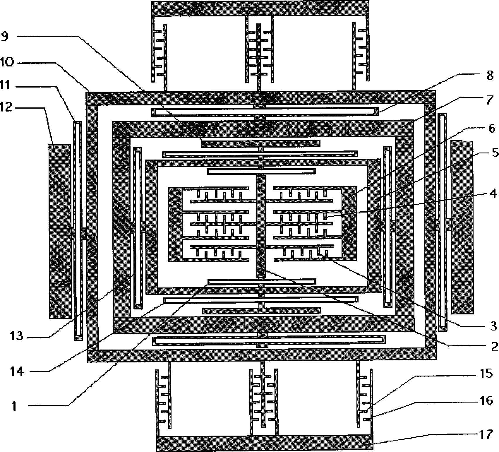
[0012] The manufacturing process of the invention roughly has the following three steps:

[0013] 1. Use ICP dry etching on the back of the silicon to etch the mesa (8 fixed blocks) required for bonding;

[0014] 2. Use electrostatic bonding to bond the bonding mesa etched in step 1 on the glass substrate to form 8 fixed blocks;

[0015] 3. Use ICP to etch the beam, mass, fixed and movable electrode patterns of the sensor on the front of the silicon to release the beam, mass and electrode structure.

[0016] The present invention will be described in more detail below in conjunction with the drawings:

[0017] The composition of the dual-degree-of-freedom dual-decoupling micromechanical vibrating gyro sensor includes a driving direction bonding block 12, a driving fixed electrode bonding block 17, a detection direction bonding block 9 and a detection fixed electrode bonding block 6 bonded on a glass substrate , The driving direction bonding block is connected to the driving mass 1...


PUM


Abstract

A micromechanical vibration gyroscopic transducer with double-freedom and double-decoupling is prepared for connecting driving direction bonding block to driving mass block through elastic beam and detection direction bonding block to the first freedom detection mass block through said beam as well as driving fixed electrode to driving fixed electrode bonding block, connecting active electrode to driving mass block and detection fixed electrode to detection direction bonding block as well as detection active electrode to the second freedom detection mass block being connected with the first one then setting isolation mass block between driving mass block and the first freedom detection mass block.

Description

(1) Technical field [0001] The invention relates to a sensor structure, in particular to a micromechanical vibration gyro sensor. (2) Background technology [0002] Micro-mechanical inertial meters based on micro-electromechanical systems (MEMS) have the advantages of small size, low cost, and compatibility with integrated circuits, so they have broad application prospects. [0003] Micromechanical gyroscope is a hot spot in the field of MEMS research in recent years. Vibrating micro-machined gyroscope is the main one. It is a microstructure based on the principle of Coriolis force. The working state of this type of gyroscope is affected by factors such as the quality and accuracy of the process, the temperature, air pressure, and damping during operation. There is a big compromise between the sensitivity of this gyro and the natural frequency of the detection mode and the natural frequency of the driving mode. In addition, there will be a certain coupling error between the drivi...

Claims


Application Information

Patent Timeline
Patent Type & Authority Applications(China)
IPC IPC(8): G01C19/56G01C19/5684
Inventor 刘晓为陈伟平尹亮唐佳禄谭晓昀
Owner HARBIN INST OF TECH
Why Eureka
Try Eureka