Worm and screw processing device

A processing equipment and screw technology, applied in the field of screw processing equipment and worms, can solve the problems of affecting the consistency of the processing quality of the worm screw, reducing the processing accuracy of the worm screw, and high equipment cost, and achieving a simple structure and consistent threads. The effect of good sex and easy operation

Inactive Publication Date: 2007-10-17
ZHEJIANG LINIX MOTOR
View PDF1 Cites 18 Cited by
  • Summary
  • Abstract
  • Description
  • Claims
  • Application Information

AI Technical Summary

Problems solved by technology

[0004] The purpose of the present invention is to provide a worm screw processing milling machine with high processing precision, good quality consistency of the processed worm screw, simple structure, low cost, and easy operation, which solves the problem of existing worm screw processing equipment in the prior art. The movement of the tool reduces the precision of the worm screw machining, which affects the consistency of the processing quality of the worm screw or the existing special processing equipment for the worm screw has problems such as complex structure, high equipment cost, and high difficulty in operation.

Method used


Image

  • Worm and screw processing device
  • Worm and screw processing device
  • Worm and screw processing device

Examples


Embodiment 1

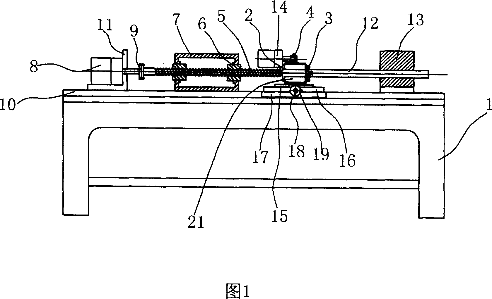
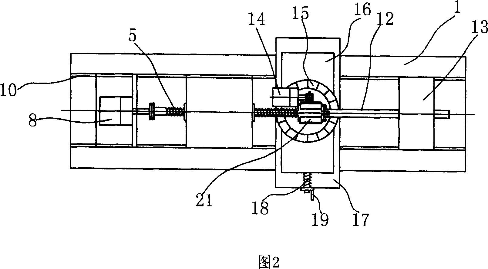
[0020] Embodiment 1: As shown in Figure 1 and Figure 2, a worm screw machining milling machine includes a bed 1, a workpiece fixture composed of a driving chuck 2 and a driven chuck 3 oppositely arranged and corresponding to the workpiece The tool 4 on the side of the workpiece is clamped by the fixture, and the workpiece feed mechanism for driving the workpiece fixture to rotate and axially translate includes a movable threaded body 5 and a static threaded body 6 fixed on the bed 1 that are threaded to each other. The threaded body 5 is represented here as a screw rod, and the static threaded body 6 is represented here as one or two nuts coaxially fixed by the nut base 7 which are matched with the screw thread. The tool 4 is represented here as a circular milling cutter. , One end of the movable threaded body 5 and the output end of the feed power source 8 are drivingly connected through a coupling 9, and the other end of the movable threaded body 5 is fixedly connected with the ...

Embodiment 2

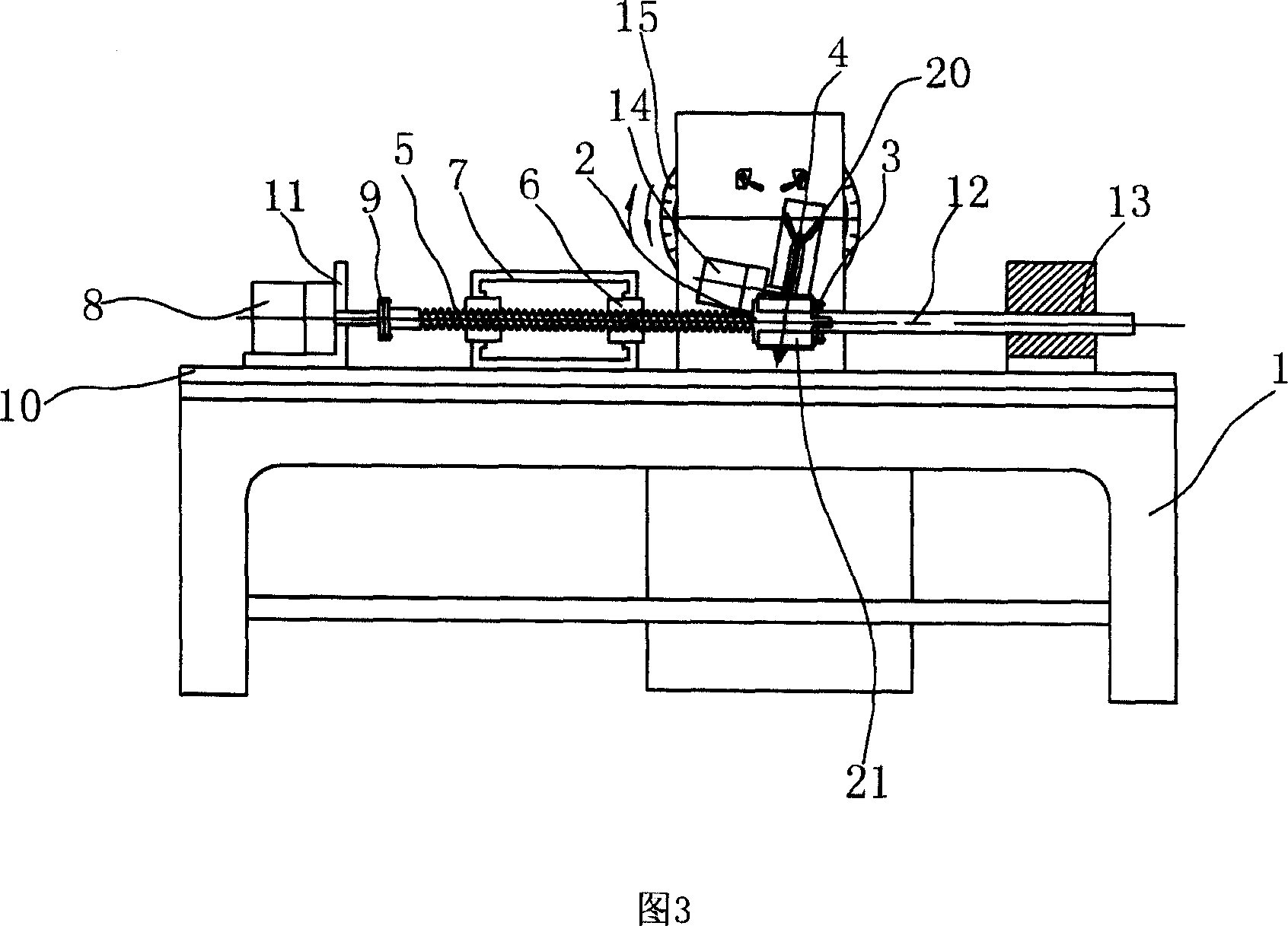
[0023] Embodiment 2: As shown in Figures 3 and 4, a worm screw machining grinder includes a bed 1, a workpiece fixture composed of a driving chuck 2 and a driven chuck 3 oppositely arranged and corresponding to the workpiece The tool 4 on the side of the workpiece is clamped by the fixture, and the workpiece feed mechanism for driving the workpiece fixture to rotate and axially translate includes a movable threaded body 5 and a static threaded body 6 fixed on the bed 1 that are threaded to each other. The threaded body 5 is represented here as a screw rod, and the static threaded body 6 is represented here as one or two nuts coaxially fixed by the nut base 7 which are fitted with the screw rod. The tool 4 is represented here as a circular grinding wheel. Diamond pens 20 for repairing the grinding wheel are respectively provided on both sides of the circular grinding wheel. One end of the movable threaded body 5 is connected to the output end of the feed power source 8 through a co...


PUM


Abstract

The invention relates to a worm lead screw processing equipment, belonging to the worm and lead screw processing equipment technology field, comprising a bed and a workpiece fixture, cutters corresponding to one side of workpiece fixture for clamping the workpiece and a workpiece feeding mechanism for driving the workpiece fixture to rotate and axially translate. The workpiece feeding mechanism at least comprises a dynamic thread body and a static thread body fixed on the bed which are match with each other by thread, wherein one end of the dynamic thread body is driving connected with an output end of a power supply, and the other end of the dynamic thread body is fixing connected with the workpiece fixture. The invention has advantages of high machining precision, simple structure, low cost, convenient operation and good quality consistency of the processed worm lead screw.

Description

Technical field [0001] The invention relates to a worm screw processing equipment, belonging to the technical field of worm and screw processing equipment. Background technique [0002] A semi-automatic external thread rolling tool (patent number: CN86102147), consisting of an eccentric shaft, a hollow gear shaft, an adjustment plate, a main body, a rolling knife, a handle, a tie rod, a length stopper, a slider, a cover, a shell, and a cone Handle and other components. The above-mentioned patented solution uses the axial feed method to process external threads. During the machining process, the tool moves but the workpiece does not move. The movement of the tool reduces the precision of thread processing and affects the consistency of thread processing quality. [0003] In the prior art, special equipment for processing the worm screw with complex structure is also used to process the worm screw, which is expensive and difficult to operate. Summary of the invention [0004] The ...

Claims


Application Information

Patent Timeline
Patent Type & Authority Applications(China)
IPC IPC(8): B23G1/02B23Q5/22B23Q1/25B23Q3/00B23G1/32B23G1/36B23Q1/01
CPCB23G1/02B24B19/022B23G1/34B23C3/32
Inventor 郭文西崔同磊
Owner ZHEJIANG LINIX MOTOR
Why Eureka
Try Eureka