Assembling corridor for vacuum pipe traffic

A technology of vacuum pipelines and corridors, which is applied in the field of rail transit and vacuum pipeline transportation, which can solve the problems of bulky loading and unloading and partition equipment, complicated operation, and high energy consumption, and achieve short train stay time at the station, small size, and low energy consumption Effect

Inactive Publication Date: 2007-10-17
SOUTHWEST JIAOTONG UNIV
View PDF0 Cites 27 Cited by
  • Summary
  • Abstract
  • Description
  • Claims
  • Application Information

AI Technical Summary

Problems solved by technology

Although this solution takes up less space, the loading and unloading and partitioning equipment

Method used


Image

  • Assembling corridor for vacuum pipe traffic
  • Assembling corridor for vacuum pipe traffic

Examples


Embodiment 1

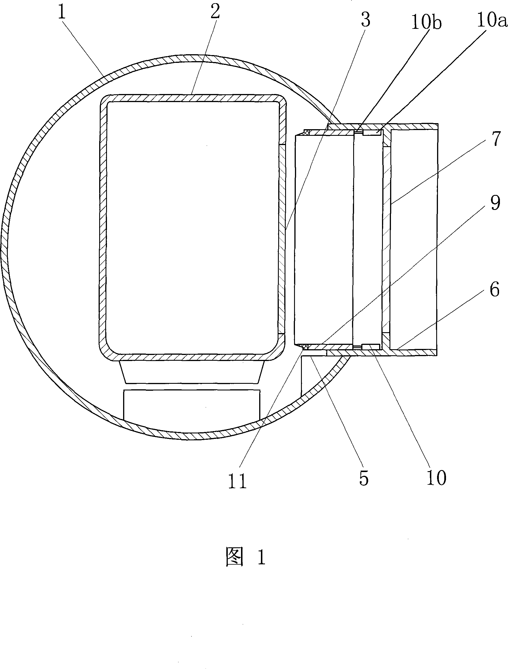
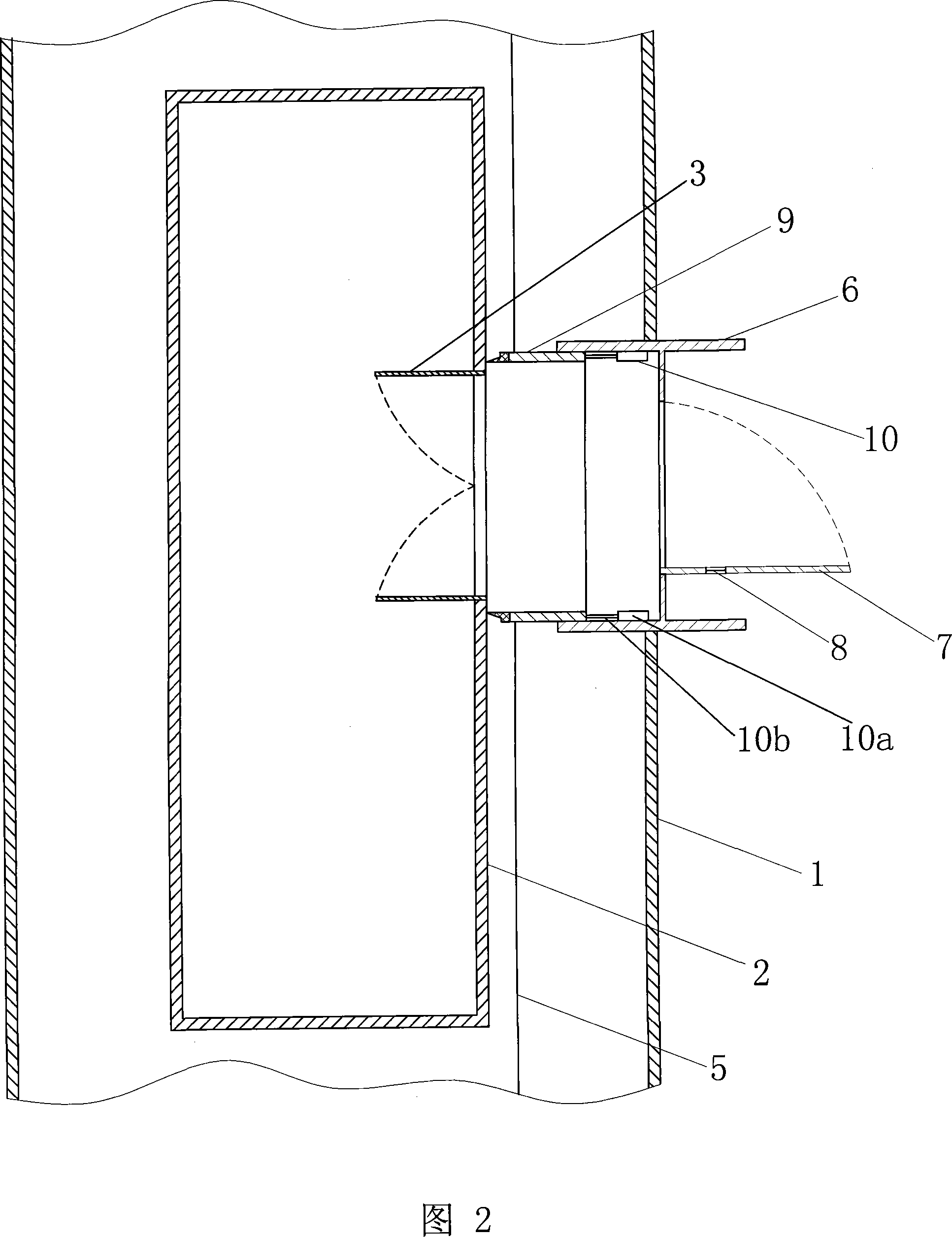
[0017] Figures 1 to 2 show that a specific embodiment of the present invention is: a connection corridor for vacuum pipeline traffic, which consists of: a cylindrical fixed corridor 6 with one end embedded in the vacuum pipeline 1 is provided at the station , the other end of the fixed corridor 6 is connected to the station platform, and the connection between the fixed corridor 6 and the vacuum pipe 1 is sealed; the inner wall of the front part of the fixed corridor 6 is sealed and fitted with the telescopic corridor 9; one end of the telescopic mechanism 10 is connected with the telescopic corridor 9, and the other end Linked to the fixed corridor 6, the inner cavity of the telescopic corridor 9 is larger than the door 3 of the train car 2, and its front end is adapted to the shape of the car around the door 3 and is provided with a sealing strip 11; the middle and rear part of the fixed corridor 6 is provided with a sealed door 7 , an air valve 8 is provided on the fixed cor...

Embodiment 2

[0020] This embodiment is basically the same as the first embodiment, except that the telescopic mechanism 10 is a rack and pinion telescopic mechanism. For making the space in the corridor succinct and attractive in appearance, the rack can be arranged below the bottom wall of the telescopic corridor 9, and the gear is located on the platform ground below the rack, and the driving device of the gear is also located on the platform 5 ground.

[0021] The fixed corridor 6 behind the airtight door of the present invention has no substantial function to the work of the present invention, and the length can be long or short, or even zero.

[0022] A plurality of connection corridors of the present invention can be installed simultaneously at the same station, and the specific number is determined according to the size of the train carriage door and the platform.


PUM


Abstract

The invention discloses a plugging corridor used for the vacuum pipe traffic, which comprises: a tube-shape fixed corridor (6) is equipped in station department with one end embedded in a vacuum pipe (1), and another end is connected with the station platform, junction of the fixed corridor (6) and vacuum pipe (1) is sealed; a telescopic corridor (9) is sealing nested in anterior inner wall of the fixed corridor (6); One end of the flexible mechanism (10) is linked with the telescopic corridor (9), and another end is connected with the fixed corridor (6), and the front end of telescopic corridor (9) fits the peripheral shape around the door (3) of the train carriage (2) and is equipped with sealing strip (11); The middle rear part of the fixed corridor (6)is equipped with a sealing door (7), one pneumatic valve (8)is provided on the sealing door (7) or the fixed corridor (6) wall before the sealing door (7). Within a short period of time, it can accomplish getting on or off of passengers in vacuum pipe, and improves the running efficiency of train with little power consumption and simple structure.

Description

technical field [0001] The invention belongs to the technical field of rail transportation, in particular to the technical field of vacuum pipeline transportation. Background technique [0002] Vacuum pipeline transportation is to set up pipelines underground or on the ground, lay maglev tracks in the pipelines, and evacuate them into a vacuum, so that the maglev vehicles can run in the vacuum pipelines. Since the maglev vehicles themselves have no mechanical friction, there is no air resistance in the vacuum pipelines. Therefore, the running speed of this maglev vehicle will be faster than any rail transit train, which is a development direction of rail transit. At present, the vacuum pipeline transportation station suitable for vacuum pipeline transportation has the following two methods: 1. By adding a bypass next to the vacuum pipeline, a transition cabin (isolation room) is built on the bypass to balance the air pressure inside the pipeline and outside the pipeline , i...

Claims


Application Information

Patent Timeline
IPC IPC(8): B61B1/02
CPCB61B13/10B61B1/02
Inventor 董安然于小娟孟凡平李怀龙
Owner SOUTHWEST JIAOTONG UNIV
Why Eureka
Try Eureka