Drying, reforming and transmission device for textile

A conveying device, textile technology, applied in textiles and papermaking, conveyors, transportation and packaging, etc., can solve problems such as affecting operation, reducing output, being torn, etc., to achieve a wide range of application width, improve product quality, operation handy effect

Inactive Publication Date: 2007-10-17
刘义涛
View PDF0 Cites 16 Cited by
  • Summary
  • Abstract
  • Description
  • Claims
  • Application Information

AI Technical Summary

Problems solved by technology

[0002] For the beauty and flatness of textiles, it is usually necessary to glue, dry and shape. When drying and shaping, the textiles are conveyed by a conveying device in a large oven, sequentially from gluing, drying to rolling. The existing conveying device consists of conveying sprockets and The conveyor chain constitutes a transmission ring, and the conveyor belt composed of two transmission rings is displaced under the action of the motor through the transmission sprocket and the transmission chain. The conveying device is installed in a large oven, and a mesh belt driven by the motor is installed between the two transmission rings; During drying and shaping transportation, the two sides of the textile are hung on the conveyor chain, and the middle of the textile is supported by the mesh belt; such a conveying method exists: ①When the transmission rings on both sides are not synchronized, the textile is easy to slip or be torn;② When the mesh belt and the transmission ring are not synchronized, the cloth surface will be bent on the textile, which will affect the product quality; ③The textile with a small width is not easy to be transported, dried and shaped, which limits the scope of use; ④Adjust the synchronous operation of the conveyor belt and the mesh belt Difficulty, affecting operation, reducing output

Method used


Image

  • Drying, reforming and transmission device for textile
  • Drying, reforming and transmission device for textile
  • Drying, reforming and transmission device for textile

Examples


Embodiment Construction

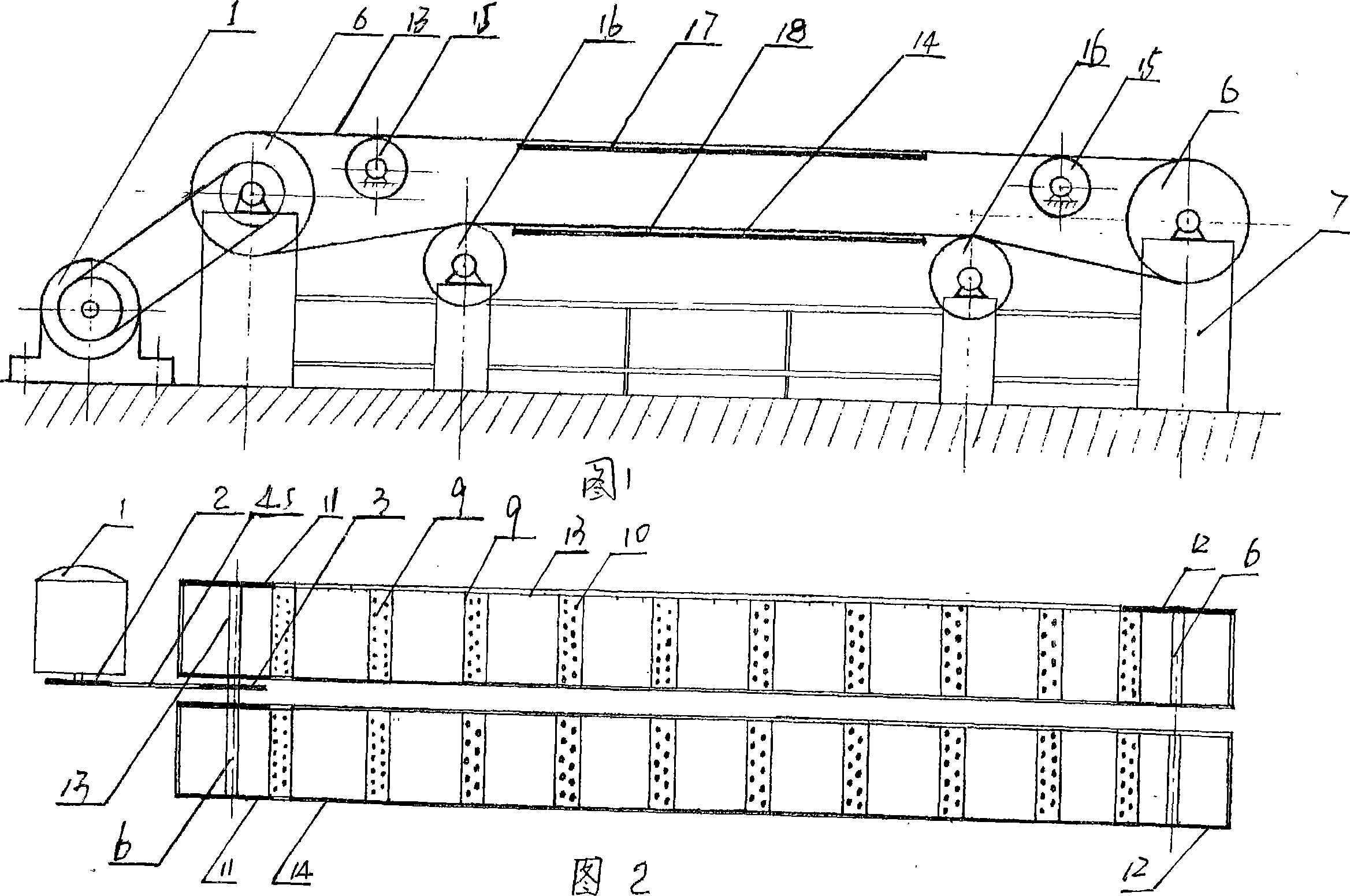
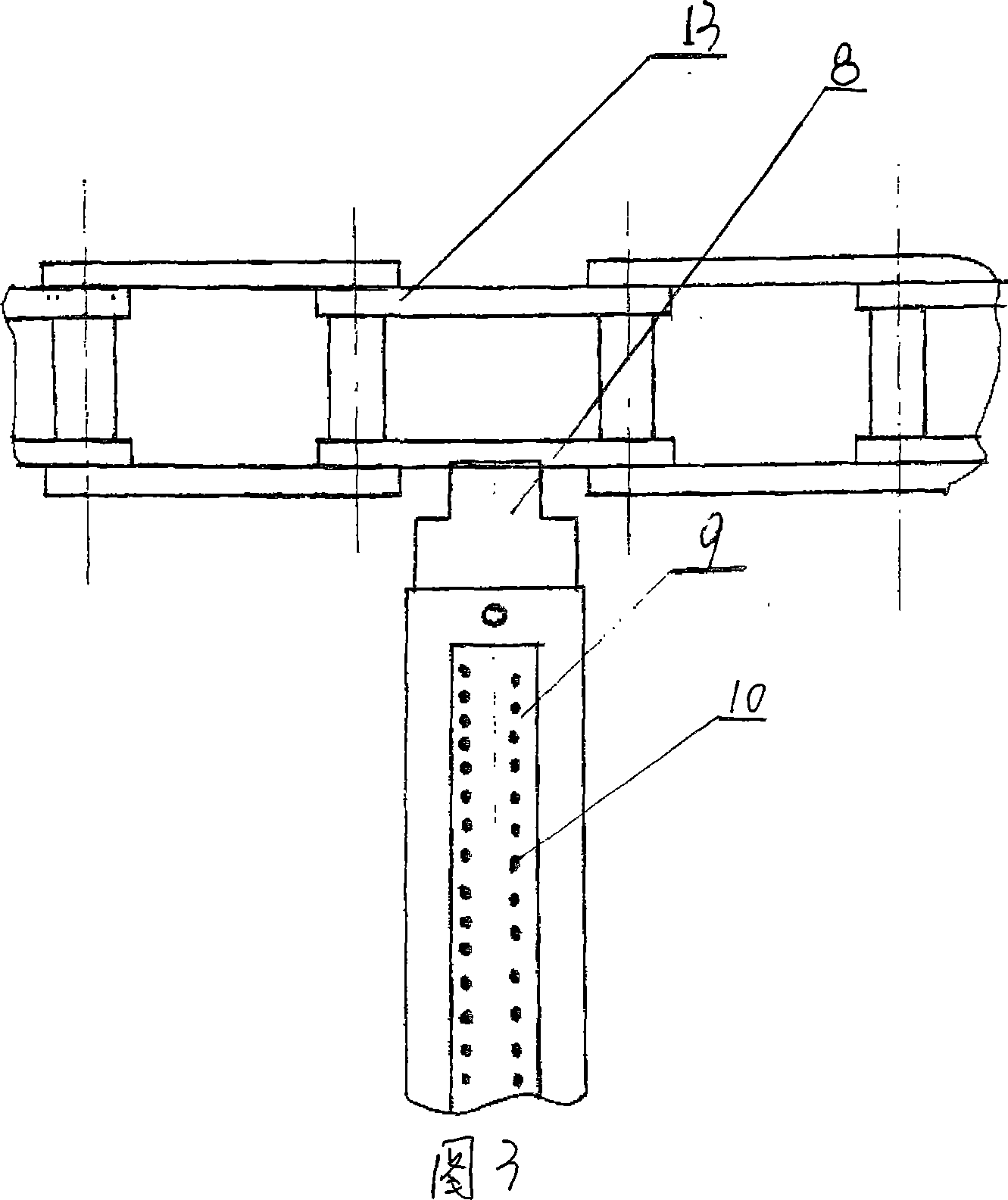
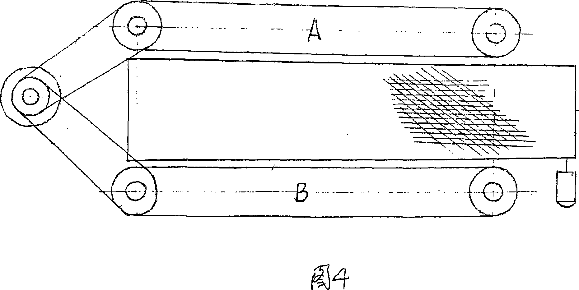
[0014] As shown in Figures 1, 2, and 3, a transmission shaft 6 is installed on both ends of the frame 7, and conveyor sprockets 11, 12 are installed on the transmission shaft 6, and the conveyor chain 13 is wrapped around the conveyor sprockets 11, 12 to form a transmission ring. , the two drive rings installed on the frame form the conveyor belt, the shaft of the motor 1 and the transmission shaft 6 are equipped with double drive sprockets 2, 3, and the double drive sprockets 2, 3 are surrounded by drive chains 4, 5. It is characterized in that a group of needle plates 8 are installed at intervals on the two conveying chains 13 and 14, and the two ends of the needle plates 8 are respectively installed on the conveying chains 13 and 14 of the two transmission rings, wherein the needle plates 8 are supported by Plate 9 and locating pin 10 form, and locating pin 10 is installed on supporting plate 9 to form needle plate 8, and the two ends of supporting plate 9 are installed on t...


PUM


Abstract

The invention discloses a drying, reforming and transmission device for textile. A transmission shaft (6) is mounted at two ends of a frame (7), transmission chain wheels (11, 12) are equipped on the transmission shaft (6), transmission chains (13) are around the transmission chain wheels (11, 12) to constitute transmission rings, the two transmission rings constitutes a conveying belt, double transmission chain wheels (2, 3) are mounted on a shaft of a motor (1) and the transmission shaft (6), and the double transmission chain wheels (2, 3) are wrapped with transmission chains (4, 5). Characteristic of the invention is that: a set of needle plates (8) are mounted on the two transmission chain (13, 14) alternately, two ends of the needle plates (8) are separately mounted on the transmission chain (13, 14) of the two transmission rings, the needle plates (8) include pallets (9) and positioning needles (10), and the positioning needles (10) are mounted on the pallets (9) to constitute the needle plates (8).Advantages of the invention are: operation is convenient, adjustment is simple, transmission is stable, deforming and bend grain are not generated, application is wide, and product quality is increased.

Description

technical field [0001] The invention relates to a conveying device, in particular to a textile drying and shaping conveying device. Background technique [0002] For the beauty and flatness of textiles, it is usually necessary to glue, dry and shape. When drying and shaping, the textiles are conveyed by a conveying device in a large oven, sequentially from gluing, drying to rolling. The existing conveying device consists of conveying sprockets and The conveyor chain constitutes a transmission ring, and the conveyor belt composed of two transmission rings is displaced under the action of the motor through the transmission sprocket and the transmission chain. The conveying device is installed in a large oven, and a mesh belt driven by the motor is installed between the two transmission rings; During drying and shaping transportation, the two sides of the textile are hung on the conveyor chain, and the middle of the textile is supported by the mesh belt; such a conveying method...

Claims


Application Information

Patent Timeline
Patent Type & Authority Applications(China)
IPC IPC(8): D06C7/00B65H20/00B65G17/06B65G21/22B65G23/44
Inventor 刘义涛
Owner 刘义涛
Why Eureka
Try Eureka