Adjustable cantalever type dynamic pressure gas elastic foil bearing

An elastic foil and cantilever type technology, applied in the field of dynamic pressure gas elastic foil bearings, can solve the problems of low bearing capacity, poor bearing stability, bearing lubrication gas end leakage, etc., to improve the bearing capacity and improve the equivalent Stiffness, effect of reducing leakage

Inactive Publication Date: 2007-10-17
HARBIN INST OF TECH
View PDF0 Cites 23 Cited by
  • Summary
  • Abstract
  • Description
  • Claims
  • Application Information

AI Technical Summary

Problems solved by technology

[0003] In order to solve the problems of the existing cantilever type dynamic pressure gas elastic foil bearings, such as bearing lubricating gas end leakage, low bearing capac

Method used


Image

  • Adjustable cantalever type dynamic pressure gas elastic foil bearing
  • Adjustable cantalever type dynamic pressure gas elastic foil bearing
  • Adjustable cantalever type dynamic pressure gas elastic foil bearing

Examples


specific Embodiment approach 1

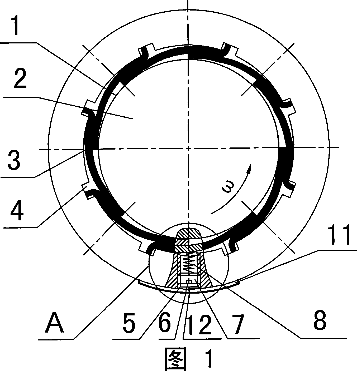
[0007] Specific embodiment one: As shown in Figure 1, the new adjustable cantilever type dynamic pressure gas elastic foil bearing of this embodiment is composed of a bearing housing 1, an elastic foil 3, and an adjustable mechanism 9; the elastic foil described 3 is mounted on the inner wall of the bearing housing 1 and evenly arranged along the inner wall of the bearing housing 1. One end of the elastic foil 3 is fixedly installed in the longitudinal groove 4 provided on the inner wall of the bearing housing 1. The elastic foil 3 The other end of the other end is overlapped on the adjacent elastic foil; the adjustable mechanism 9 is installed in the internal threaded through hole 5 of the housing 1 and screwed with the threaded through hole 5, and the adjustable mechanism 9 is in contact with the elastic foil 3 . During use, journal 2 is contained on the bearing.

specific Embodiment approach 2

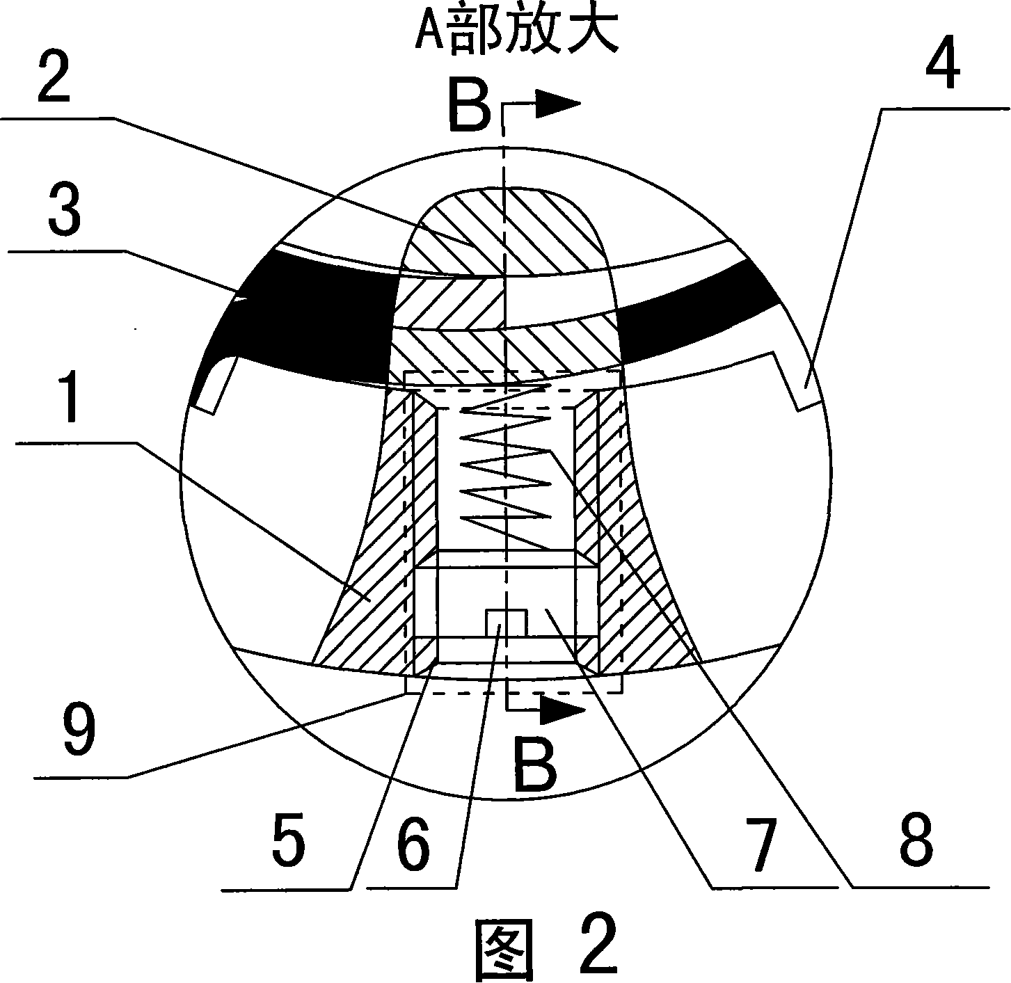
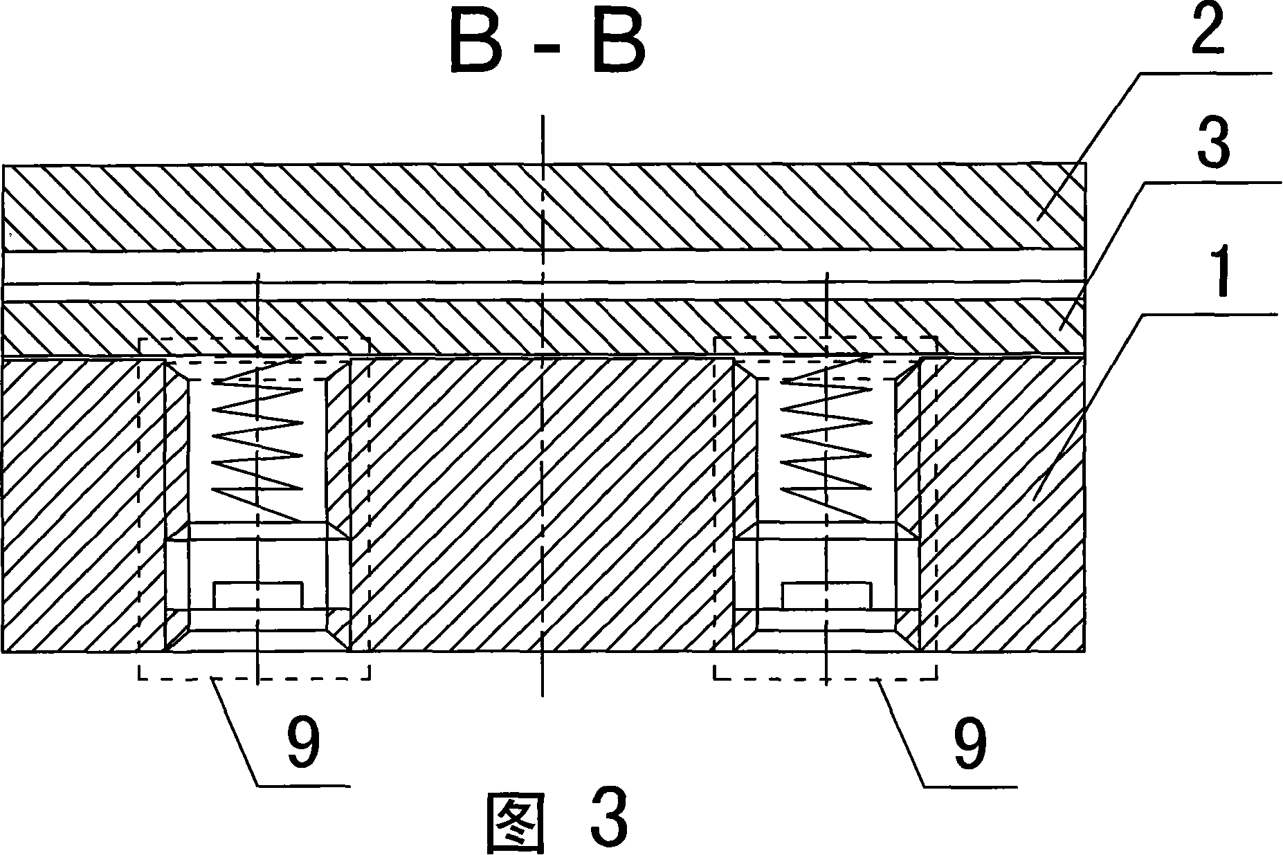
[0008] Specific embodiment two: as shown in Figure 2, the adjustable mechanism 9 described in this embodiment is composed of a cylindrical plug 7 and a cylindrical spring 8, the inner end of the cylindrical plug 7 is in contact with the outer end of the cylindrical spring 8, and the cylindrical The outer end surface of the plug 7 is provided with a square groove 6, and the square groove 6 is convenient for the adjustment of the cylindrical plug 7 in and out. This structure is simple and easy to process. Other components and connections are the same as those in the first embodiment.

specific Embodiment approach 3

[0009] Specific embodiment three: the adjustable mechanism 9 described in this embodiment is composed of a cylindrical long wire plug 10, a thin steel wire rod 13 and a cylindrical spring 8, the inner end of the cylindrical long wire plug 10 is in contact with the outer end of the cylindrical spring 8, The cylindrical long screw plug 10 is radially provided with a first locking through hole 10-1 and a second locking through hole 10-2 perpendicular to each other, and a thin steel wire rod 13 is inserted into the radial first locking hole. In the tight through hole 10 - 1 or the second locked through hole 10 - 2 , a first square groove 14 is provided on the outer end surface of the cylindrical long thread plug 10 . This structure can effectively adjust the compression amount of the cylindrical spring 8 and has a first locking through hole 10-1 and a second locking through hole 10-2. The structure is simple and compact, and the locking effect is good. Other components and connect...


PUM


Abstract

A new type adjustable cantalever type aerodynamic elastic foil bearing relates to an aerodynamic foil bearing. The present invention solves the problems that the existing cantalever type aerodynamic foil bearing will leak bearing lubricate gas, and has low bearing force and bad stability in high speed. The elastic foil (3) is mounted on the inner wall of a bearing housing (1) and is uniformly distributed along the inner wall of the bearing housing (1), one end of the elastic foil (3) is fixed in a longitudinal groove (4) disposed on the inner wall of the bearing housing (1), and another end of the elastic foil (3) is superposed on an adjacent elastic foil. It is characterized in that the bearing also includes an adjustable mechanism (9) which is mounted in a screw thread through hole (5) on the housing (1) and is connected with the elastic foil (3). The present invention improves the equivalent rigidity and equivalent damping of the elastic foil by the adjustable mechanism and thereby greatly improves the bearing ability and stability of the bearing.

Description

technical field [0001] The invention relates to a dynamic pressure gas elastic foil bearing. Background technique [0002] Cantilever type (ie: Garrett type) dynamic pressure gas elastic foil bearing has a low load capacity and poor stability at high speeds, which seriously limits the application and further promotion of this type of bearing in low temperature engineering, precision machining, aerospace, national defense and other fields . The limited rigidity of the elastic foil, a large amount of end leakage of lubricating gas, and the small damping and weak damping ability of the elastic foil are the direct reasons for the low bearing capacity and poor stability of this bearing. Contents of the invention [0003] In order to solve the problems of the existing cantilever type dynamic pressure gas elastic foil bearings, such as bearing lubricating gas end leakage, low bearing capacity, and poor bearing stability at high speed, the present invention further provides a nov...

Claims


Application Information

Patent Timeline
IPC IPC(8): F16C17/02F16C33/02F16C33/74
Inventor 刘占生许怀锦
Owner HARBIN INST OF TECH
Why Eureka
Try Eureka