

Permanent-magnetic biased axial magnetic bearing
A technology of axial magnetic bearing and permanent magnet bias, which is applied in the direction of shafts and bearings, bearings, engine components, etc., can solve the problems of high power consumption and difficulty in radial torsion control, and achieve low power consumption and reduced Effects of power consumption and axial size reduction
- Summary
- Abstract
- Description
- Claims
- Application Information
AI Technical Summary
Problems solved by technology
Method used
Image

Examples
Embodiment Construction
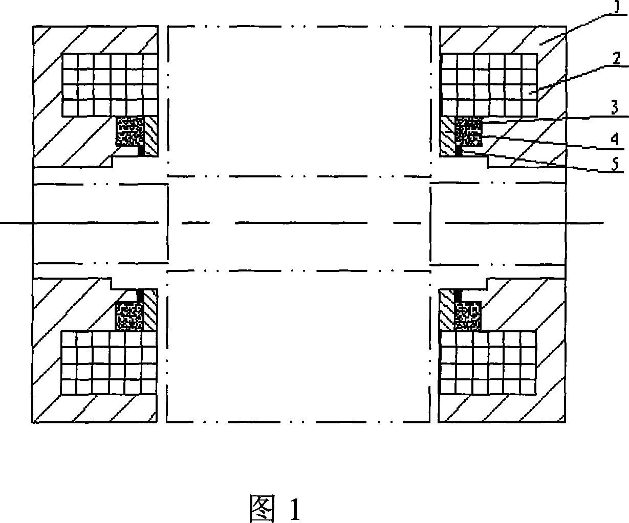
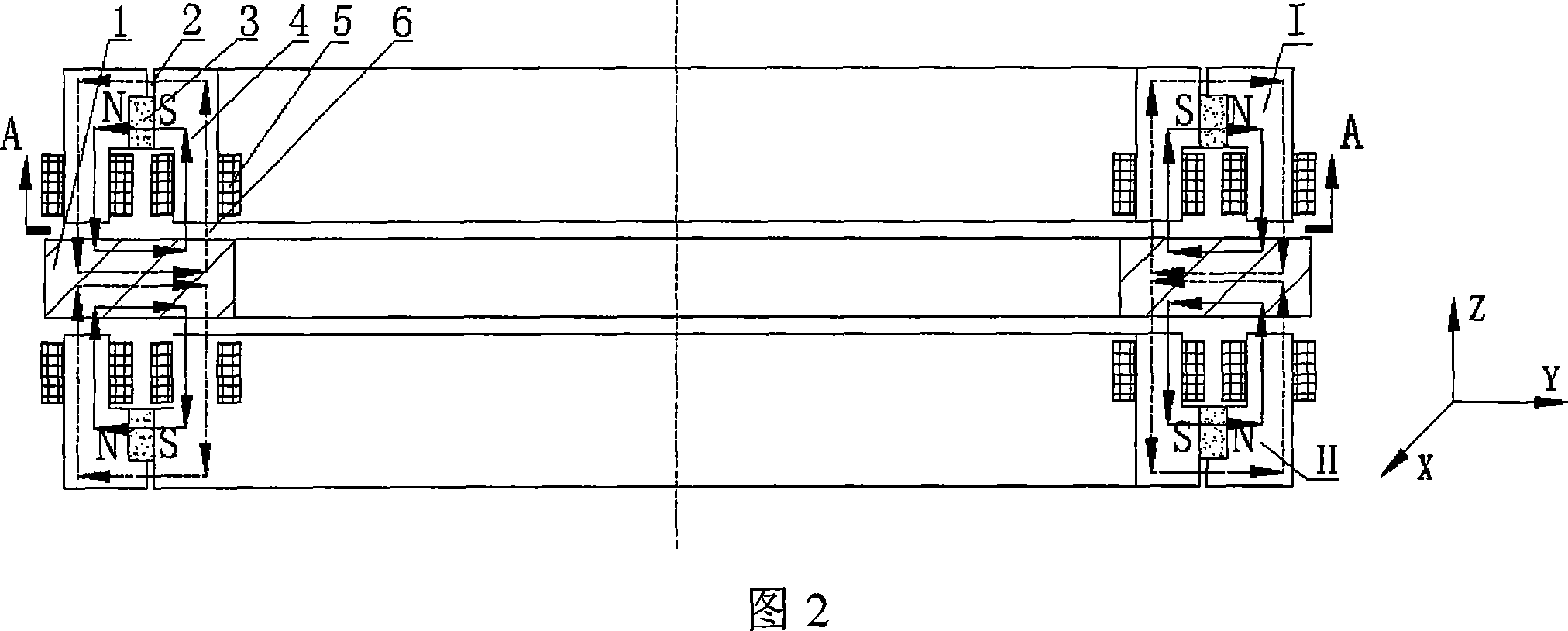
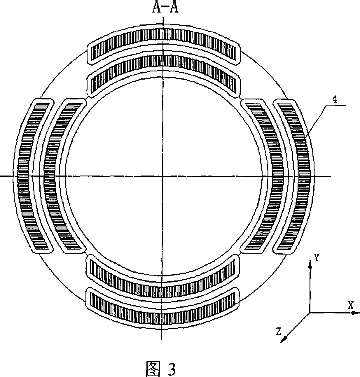
[0013]As shown in Fig. 2 and Fig. 3, the present invention is made up of stator part and rotor 1, and stator part is made up of 4 groups of stator cores 4, permanent magnet 3 and coil 5, and 4 groups of stator cores 4 constitute 8 stators on the whole circumferential direction The magnetic poles of the stator core are placed along the directions of +X, -X, +Y, and -Y. In order to increase the cross-sectional area of the magnetic poles of the stator core to improve the bearing capacity of the axial magnetic bearing, the area of the magnetic poles of the stator core is made into an arc surface. A coil 5 is wound on each stator core pole, an axial magnetic air gap 6 is formed between the stator part and the rotor, an arc-shaped permanent magnet 3 is placed between the two stator core poles in each set of stator cores 4, and the permanent The magnets 3 and the two stator core poles of each set of stator cores 4 form a second air gap 2 on the outside in the radial direction. Th...
PUM
 Abstract
Description
Claims
Application Information