High light transmittance ratio touch screen

A high light transmittance, touch screen technology, applied in the touch screen field, can solve the problems of the stability of the overall light transmittance without the wear resistance of the outer layer, and achieve the effect of stable performance

Inactive Publication Date: 2007-10-17
达诺光电股份有限公司
View PDF1 Cites 16 Cited by
  • Summary
  • Abstract
  • Description
  • Claims
  • Application Information

AI Technical Summary

Problems solved by technology

[0004] To sum up, in the prior art mentioned above, all are emphasizing the performance of light transmittance and solving the difficult problems in the process, but none of them are particularly aimed at the abrasion resistance or anti-electromagnetic interference (EMI) of the outer layer of the anti-reflective optical coating layer. Or improve the stability of the overall light transmittance, and propose further solutions

Method used


Image

  • High light transmittance ratio touch screen
  • High light transmittance ratio touch screen
  • High light transmittance ratio touch screen

Examples


Embodiment Construction

[0020] Relevant preferred embodiment of the present invention and technical content, now in conjunction with accompanying drawing are described as follows:

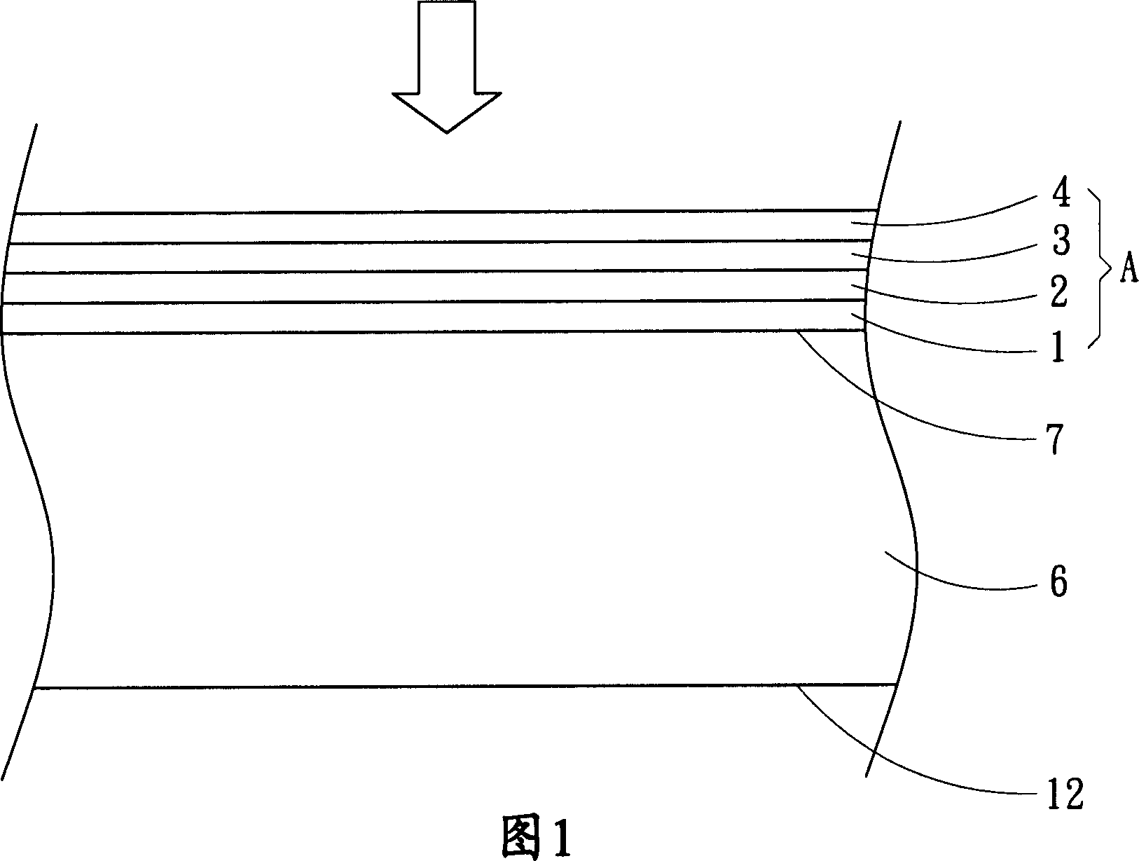
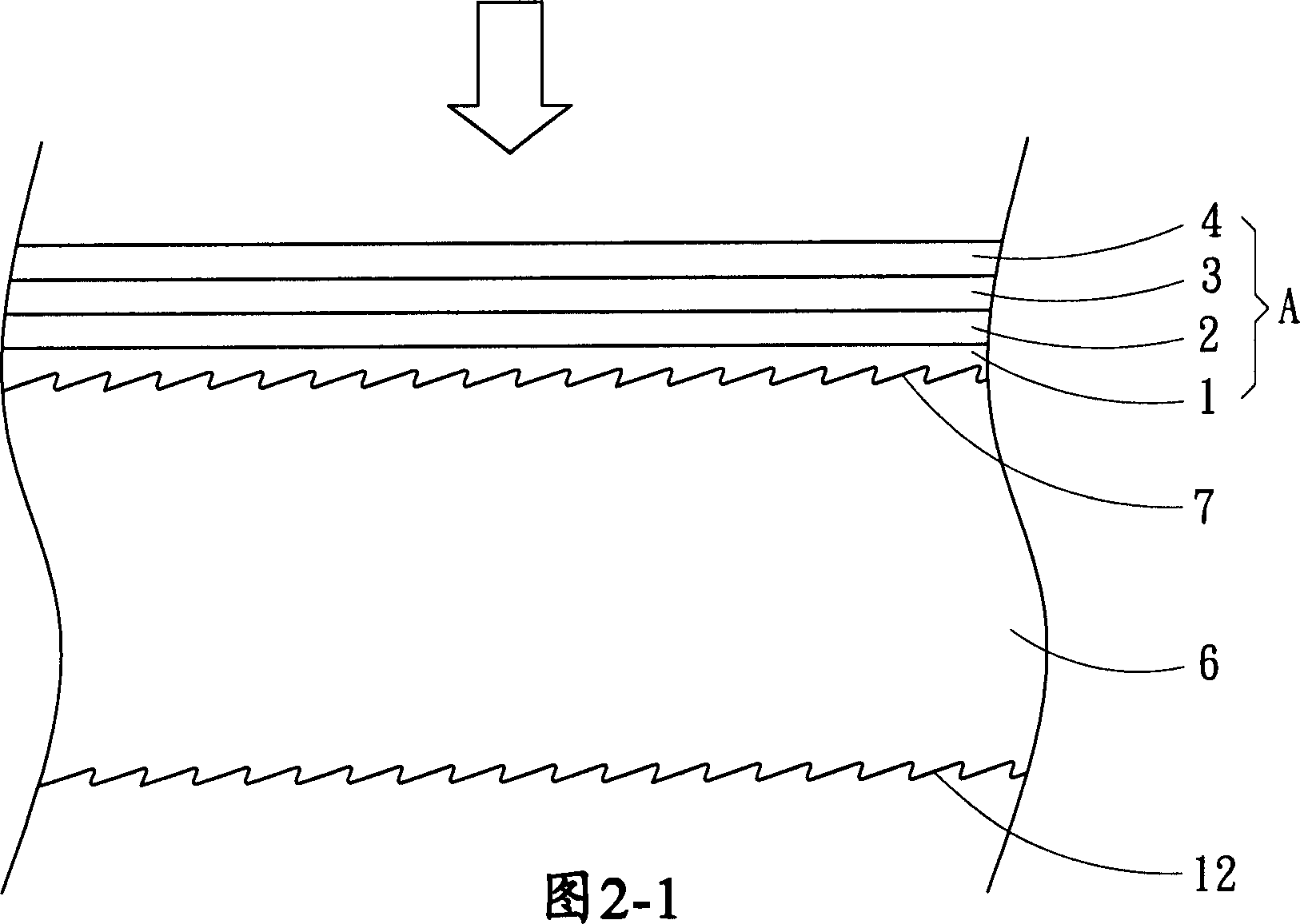
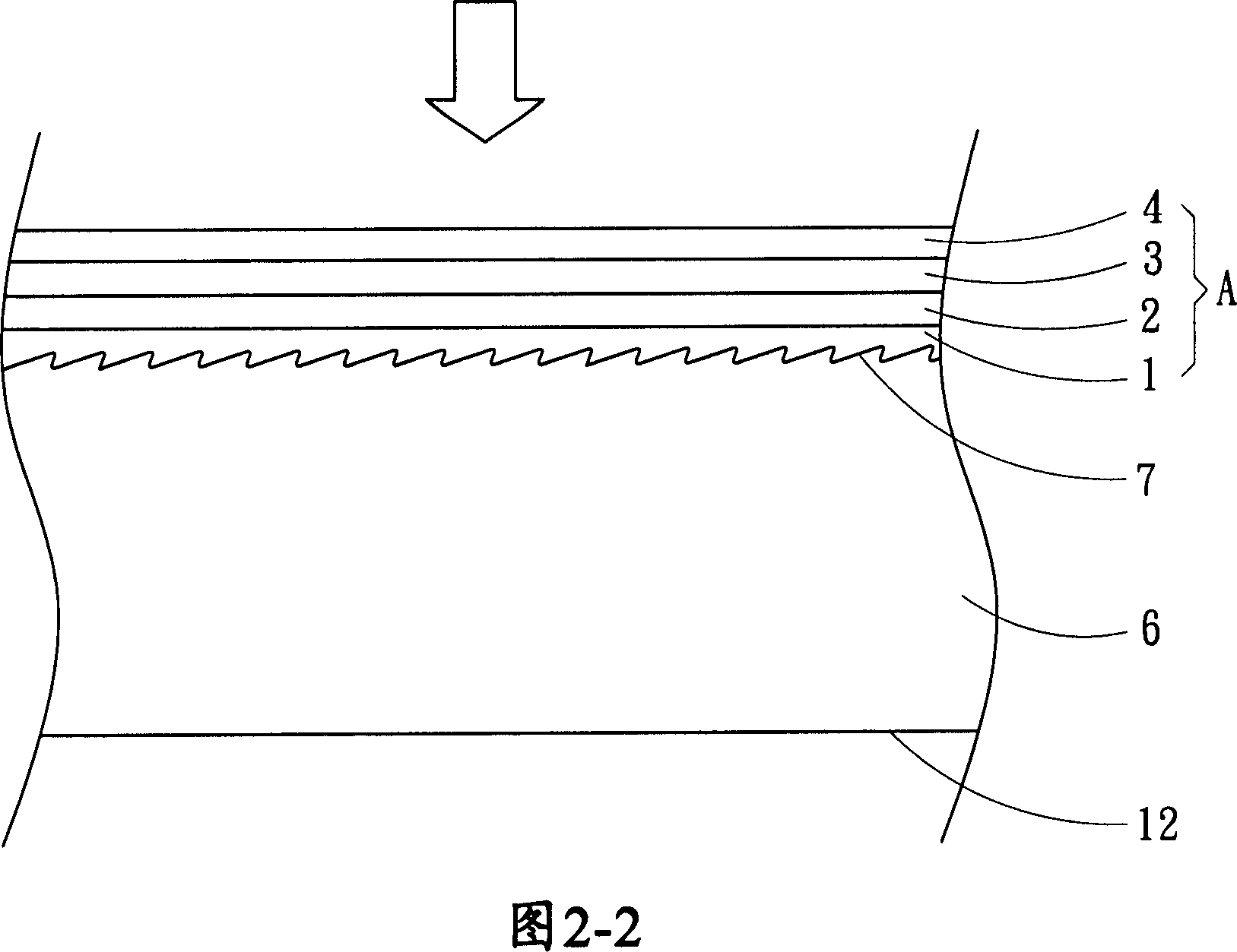
[0021] First, please refer to FIG. 1 , in the first embodiment, the high transmittance touch screen of the present invention has a substrate 6 and a first anti-reflection coating layer structure A. As shown in FIG. Wherein, the substrate 6 has a front surface 7 and a reverse surface 12 relative to the front surface 7. It is defined here that the front surface 7 refers to the side adjacent to the user, and the reverse surface 12 refers to the side adjacent to the backlight source. The substrate 6 can be It is made of glass, plastic or other transparent materials; the first anti-reflection coating layer structure A is a four-layer structure, including a first layer 1, a second layer 2, a third layer 3 and a first layer Four layers 4, and the first layer 1, the second layer 2, the third layer 3 and the fourth layer 4 are seq...


PUM

PropertyMeasurementUnit
thicknessaaaaaaaaaa
diameteraaaaaaaaaa
mean roughnessaaaaaaaaaa

Abstract

The invention discloses a high-transmittance touch screen, including a substrate and at least a multi-layer reflection configuration which is a four-layer structure coated on the front surface of the substrate with designed refractive index of high, low, high and low calculated from the side adjacent to the substrate, wherein the outer layer is a protection layer with protecting function provided with a reflective index laid between 1.3~1.5, a thickness of at least 0.1micrometre, and the hardness accorded with ASTM-D3363 international inspection standard, and due to the design of the protecting layer, the transmittance of the touch screen reaches ASTM-D1003 92% or more, and also strengthens the antiware performance of the surface.

Description

technical field [0001] The present invention relates to a touch screen with a multi-layer reflective structure, in particular to a capacitive touch screen with a protective layer as the surface layer of the multi-layer reflective structure to enhance the anti-wear effect. touch panel). Background technique [0002] Anti-reflective optical coatings were used in building materials such as glass and goggles in the past, but with the advancement of technology, this technology has gradually been transferred to semiconductors, optical disc read heads, liquid crystal displays, and touch panels. In the design principle of traditional anti-reflective optical coating layers, the layer coated on the contact substrate has a higher refractive index (i.e. H), and then faces this layer followed by another layer with a lower refractive index (i.e. L). Therefore, the structure of the traditional anti-reflection optical coating layer is H, L, H, L in order from the direction adjacent to the ...

Claims


Application Information

Patent Timeline
Patent Type & Authority Applications(China)
IPC IPC(8): G02B1/11G02B1/115
Inventor 黄聪智何斌圣陈胜宗游钦胜陈筱君张家智黎家俨
Owner 达诺光电股份有限公司
Why Eureka
Try Eureka