A power MOSFET driving circuit

A driving circuit and power technology, applied in emergency protection circuit devices, output power conversion devices, electrical components, etc.

Inactive Publication Date: 2007-10-17
INST OF SEMICONDUCTORS - CHINESE ACAD OF SCI
View PDF0 Cites 27 Cited by
  • Summary
  • Abstract
  • Description
  • Claims
  • Application Information

AI Technical Summary

Problems solved by technology

The invention is suitable for use in integrated circuits such as integrated switching power supplies and their control circuits

Method used


Image

  • A power MOSFET driving circuit
  • A power MOSFET driving circuit
  • A power MOSFET driving circuit

Examples


Embodiment Construction

[0012] Below in conjunction with accompanying drawing, the present invention will be further described

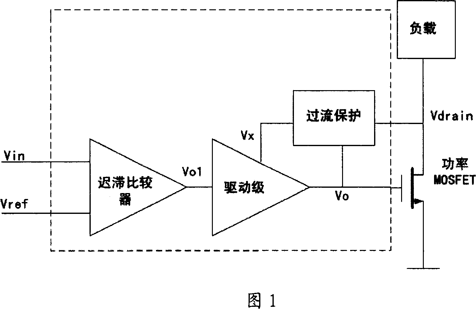
[0013] Fig. 1 is a structural block diagram of a power MOSFET driving circuit of the present invention. The input signal Vin is compared with the reference voltage Vref by the hysteresis comparator, and the logic control signal Vo1 is obtained by judgment. The drain terminal voltage Vdrain when the power MOSFET is turned on is introduced into the input terminal of the overcurrent protection circuit as an overcurrent detection, compared with the reference, and an overcurrent signal Vx is output. The logic control signal Vo1 controls the switching power stage together with the overcurrent signal Vx. When Vx is at a high level, the output of the switching power stage is at a low level, and the power MOSFET is turned off to realize over-current protection. When Vx is low level, the switching power stage output level logic is the same as the Vo1 signal.

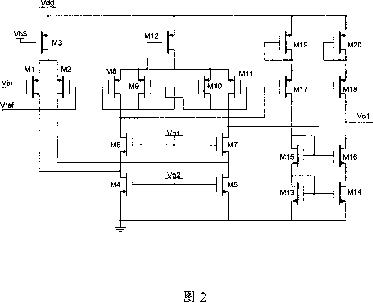
[0014] Fig. 2 is a c...


PUM


Abstract

The present invention relates to the field of the driving circuit technology that is a power MOSFET driving circuit. The power MOSFET driving circuit includes a hysteresis comparator, a switch driving stage, an over-current protection circuit module, and the hysteresis comparator compares the externally controlled signals with the reference power level to determine the control signal obtaining the switch drive, and the switch drive stage circuit makes a drive output to the power MOSFET and the drain terminal voltage when the power MOSFET is conductive is induced into the input end of the over-current protection circuit to realize the over-current protection comparing to the standard. The input signal Vin is compared with the standard current Vref through the hysteresis comparator to judges and obtains the logically controlled signal Vol which controls the switch power stage together with the over-current signal Vx to realize over-current protection, and when Vx is a low level and the output level logic of the switch power level is identical to that of the Vol signal. The present invention is adapted to the integrated circuits such as the integrated switch power supply and the control circuit thereof.

Description

technical field [0001] The invention relates to the technical field of drive circuits, in particular to a power MOSFET drive circuit that can be used in an integrated switching power supply and its control circuit. Background technique [0002] The traditional power MOSFET (metal-oxide-semiconductor field-effect transistor) drive circuit consumes additional power consumption due to the existence of simultaneous on-time of its drive stages; at the same time, the external sampling resistor method often used for overcurrent protection, due to the The MOSFET outputs a large current and consumes extra power. Contents of the invention [0003] Aiming at the above problems, the present invention proposes a power MOSFET drive circuit that avoids the simultaneous conduction of the output drive stages by controlling the delay, utilizes the drain terminal voltage when the power MOSFET is turned on to realize overcurrent protection, and does not require an external current sampling re...

Claims


Application Information

Patent Timeline
Patent Type & Authority Applications(China)
IPC IPC(8): H02M1/08H02H7/122H03K17/08H03K17/28H03K17/687
Inventor 高峰李春寄刘忠立于芳
Owner INST OF SEMICONDUCTORS - CHINESE ACAD OF SCI
Why Eureka
Try Eureka