Regeneration and brake management system

A regenerative power system, regenerative braking technology, applied in electric braking systems, brake control systems, brakes, etc., can solve problems such as reducing vehicle stability, brake wear, uneven tires, etc.

Inactive Publication Date: 2007-10-17
EATON INTELLIGENT POWER LIMITED
View PDF0 Cites 19 Cited by
  • Summary
  • Abstract
  • Description
  • Claims
  • Application Information

AI Technical Summary

Problems solved by technology

Fourth, regeneration will unbalance the 2WD braking system, possibly causing unusual brake wear and tire wear
This unbalanced application of negative torque between the drive and n

Method used


Image

  • Regeneration and brake management system
  • Regeneration and brake management system
  • Regeneration and brake management system

Examples


Embodiment Construction

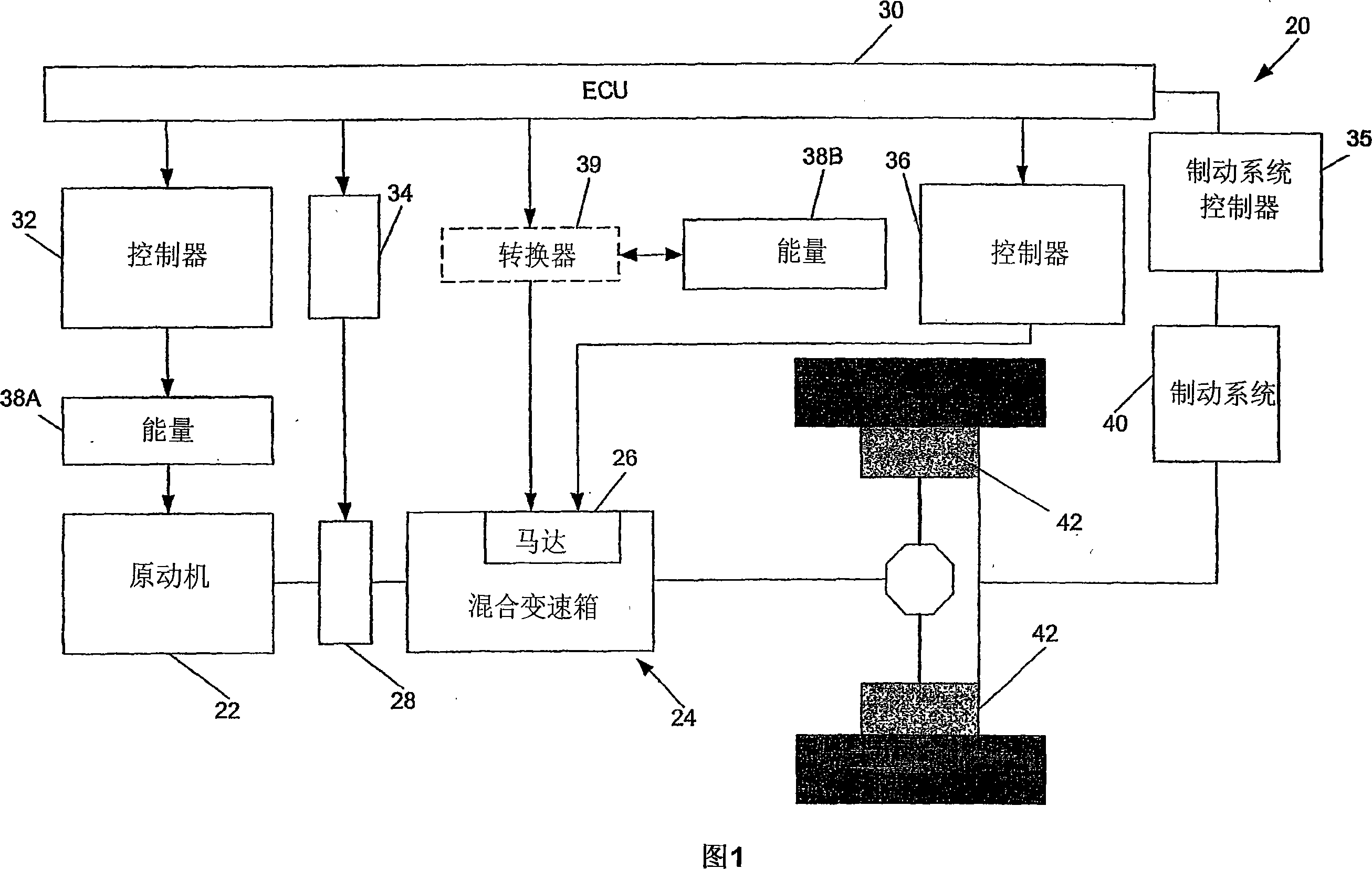
[0017] The present systems and methods provide an integral, anti-skid, hydraulic brake pressure booster and regeneration control system. Specifically, the present systems and methods are designed to maximize the energy accumulated through regenerative braking by at least partially disabling the friction brakes when sufficient deceleration can be obtained through regenerative braking. Energy regeneration is thus maximized while giving the vehicle the required amount of deceleration. In addition, the vehicle's anti-skid function is enhanced by a controller that manages and distributes the maximum allowable kinetic energy available to the battery and distributes excess energy to the appropriate friction brakes. By predicting and monitoring the torque of the regenerative device in terms of current, combined with the detection of driver pedal input intention and wheel speed information, regeneration is maximized without causing vehicle driving problems, such as wheel slippage, whic...


PUM


Abstract

A regeneration and brake management system includes a prime mover (22, 26), an energy storage device (38A, 38B) associated with the prime mover (22, 26), and a regenerative braking system (40) including a controller (32, 34, 35, 36) and at least one friction brake (42, 152, 154, 156, 158), wherein the regenerative braking system (40) is configured to at least partially disable the at least one friction brake (42, 152, 154, 156, 158) during regenerative braking.

Description

technical field [0001] The present systems and methods relate generally to hybrid vehicles and, in particular, to brake management systems adapted to regenerate a fuel source of a hybrid vehicle. Background technique [0002] Automobile manufacturers are constantly working to improve the fuel efficiency of motor vehicles. Improvements in fuel efficiency generally focus on reducing weight, improving aerodynamics, and reducing power losses in the vehicle's powertrain. However, the need to increase fuel efficiency is often offset by the need to provide greater comfort and convenience to vehicle operators. For example, a manual transmission is more fuel efficient than an automatic transmission due to lower parasitic losses. The larger losses associated with conventional automatic transmissions arise from the torque converter, disc clutches and hydraulic pumps used to control the operation of the hydraulic shifting system. However, the vast majority of domestic motor vehicles ...

Claims


Application Information

Patent Timeline
IPC IPC(8): B60K6/04B60L7/26B60K6/48B60K6/547
CPCB60T1/10Y02T10/6282B60W10/184B60K6/12B60K6/547B60L7/26B60K6/48Y02T10/6208B60W10/08Y02T10/6221B60W20/00B60T2270/604Y10S903/947F16D61/00Y02T10/62B60W30/18127B60W20/13
Inventor J·L·奥利弗
Owner EATON INTELLIGENT POWER LIMITED
Why Eureka
Try Eureka