
Welding technology for broken and waste core rod

A welding process and mandrel technology, which is applied in the field of reuse of waste mandrels, and can solve problems such as unusable waste mandrels

Active Publication Date: 2007-10-24
TIANJIN PIPE GROUP CORP
View PDF0 Cites 10 Cited by
  • Summary
  • Abstract
  • Description
  • Claims
  • Application Information

AI Technical Summary

Problems solved by technology

[0011] In order to solve the technical problem that the waste mandrel cannot be used, the purpose of the present invention is to provide a welding process for the waste mandrel,

Method used


Image

  • Welding technology for broken and waste core rod
  • Welding technology for broken and waste core rod

Examples


Embodiment Construction

[0031] The welding process of the waste mandrel of the present invention will be described in conjunction with the accompanying drawings and embodiments.

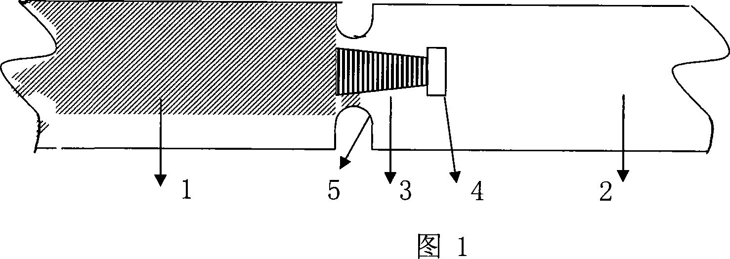
[0032] The structure of the broken mandrel after welding is shown in Figure 1. In order to ensure that there will be no broken mandrel accidents in production, reduce the welding workload, reduce the repair cost, and ensure the straightness of the mandrel. The segmental broken mandrel 1 is machined with a threaded connecting column 3 with a partial ladder buckle, and a threaded hole matching the threaded connecting column 3 with a partial ladder buckle is machined on the front section of the broken mandrel 2, and an undercut 4 is left. A U-shaped welding groove 5 is processed at the joint between the broken mandrel 1 of the rear section and the broken mandrel 2 of the front section. The advantage of the U-shaped groove is that it can save welding materials and reduce the labor intensity of welders.

[0033] Then use the ma...


PUM


Abstract

The invention relates to a broken core bar welding process that comprises the thread processing and extension, preheating and welding bar selection, heat treatment after the welding, rotary cooling and grinding. In the process of preheating and welding bar selection, it welds continuously at one time to maintain the temperature between layers. In after welding heat treatment, it is cooled gradually using heat insulating material covering the welding spot under working environment lower than 5deg.C. It uses broken core bar to weld into qualified core bar blank, after lathe processing to reach the durability of the imported ones. If there isn't any crack occur, it means that the welding has reached expectation. It reduces the imported core bar blank with reduced capital and improved productivity.

Description

technical field [0001] The invention relates to the reutilization of the waste mandrel rods interrupted by the production of steel pipes, in particular to a welding process for the broken waste mandrel rods. Background technique [0002] The mandrel is one of the main deformation tools of the limited mandrel continuous rolling mill in the pipe mill. For example, the mandrel used in the Φ250MPM continuous rolling mill has always been imported, and the value is expensive. Rational use of mandrels to fully increase the service life of mandrels is one of the important tasks to reduce production costs. [0003] The steel number of mandrel material is X35CrMOVo5 H13, its chemical composition: (%) [0004] C: 0.30——0.38 Mn: 0.60Max [0005] Si: 0.70 - 1.20 Cr: 4.50 - 5.50 [0006] V: 0.80——1.20 Mo: 1.00——1.50 [0007] S: 0.008MaxS+P: 0.02max [0008] By calculating the carbon equivalent C E At 1.88%, much higher than the ? 0.6%, extremely poor solderability. [0009] The wo...

Claims


Application Information

Patent Timeline
Patent Type & Authority Applications(China)
IPC IPC(8): B23P6/00B21B25/00
Inventor 张金钢郭会勇田志国
Owner TIANJIN PIPE GROUP CORP
Learn More